
Real-time calibration for downhole spectrometer

Active Publication Date: 2007-05-17
SCHLUMBERGER TECH CORP
View PDF19 Cites 36 Cited by
  • Summary
  • Abstract
  • Description
  • Claims
  • Application Information

AI Technical Summary

Benefits of technology

[0009] The present invention provides a number of embodiments directed towards improving, or at least reducing, the effects of one or more of the above-identified problems. According to at least one embodiment, an apparatus for performing real-time analysis of a subterranean formation fluid comprises a light source configured to transmit at least a sample signal through a sample of the subterranean formation fluid and a reference signal, at least one photodetector confi

Problems solved by technology

As known in the art, the light sources, photodetectors and processing electronics employed in conventional fluid analysis modules are typically adversely affected by the extreme temperatures experienced in downhole environments.
For example, the optical power of light sources (such as broad-spectrum incandescent light sources) tends to diminish or drift when operated at elevated temperatures.
Processing electronics, and in particular analog processing electronics, are also known to be susceptible to DC offset drift when operated at extreme temperatures.
Because an accurate estimation of the optical density of a formation fluid requires extremely precise measurements, such drifts in the light source, photodetector and / or processing electronics may result in errors in the estimation of the optical density of a formation fluid.
Although various calibration techniques for compensating for these temperature-dependent drifts and shifts are known in the art, these conventional calibration techniques are typically only performed prior to sampling and analyzing the formation fluid.
However, because the temperature of the borehole or the sampling tool frequently changes after the calibration operation has been performed, the optical density estimations calculated after such temperature changes may be erroneous.
For example, heat from the formation fluid itself, or heat generated by one or more of the components in the sampling tool during its operation, may cause the temperature of the fluid analysis module or sampling tool to change.
Any such temperature change will likely lead to the aforementioned drifts in optical power, optical gain and DC offset voltage.

Method used


Image

  • Real-time calibration for downhole spectrometer
  • Real-time calibration for downhole spectrometer
  • Real-time calibration for downhole spectrometer

Examples


Embodiment Construction

[0045] Illustrative embodiments and aspects are described below. One of ordinary skill in the art will appreciate that in the development of any such embodiment, numerous implementation-specific decisions must be made to achieve the developers' specific goals, such as compliance with system-related and business-related constraints, which will vary from one implementation to another. Although such a development effort might be complex and time-consuming, the same would nevertheless be a routine undertaking for those of ordinary skill in the art having the benefit of this disclosure.

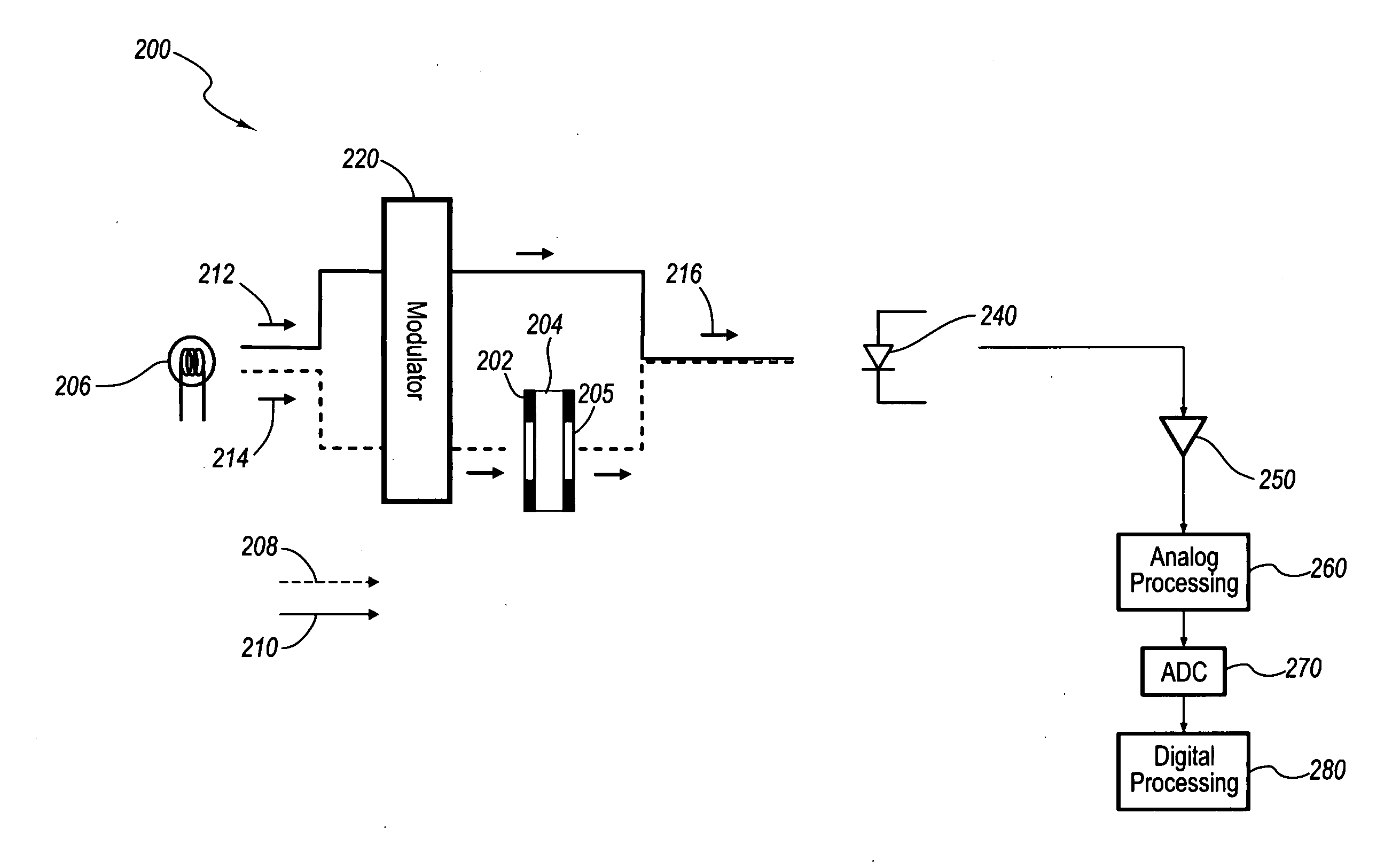
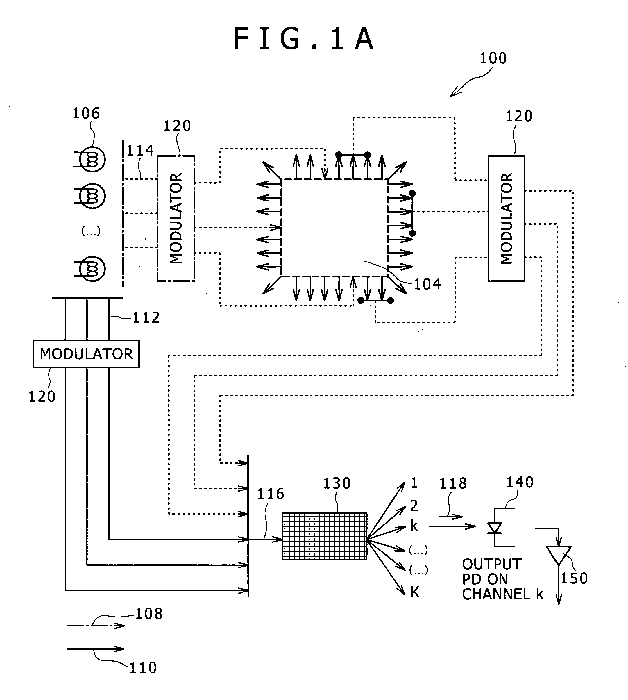
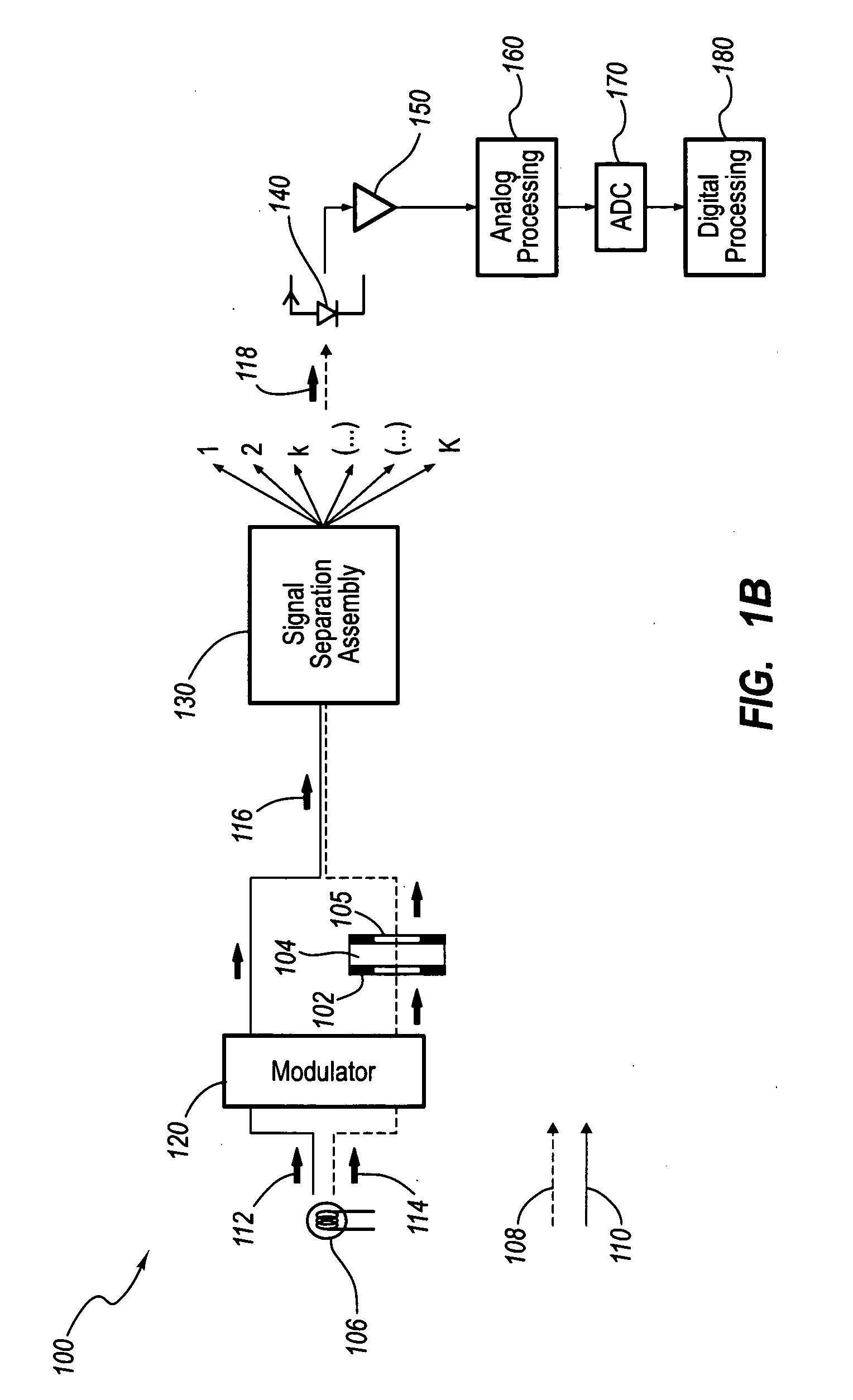
[0046]FIGS. 1A-1B are schematic diagrams of exemplary fluid analysis modules 100 for analyzing extracted samples of formation fluids. As will be appreciated by those of skill in the art, exemplary fluid analysis modules 100 may be adapted for use in a variety of environments and / or included in a number of different tools. For example, one or more fluid analysis modules 100 may form a portion of a fluid an...


PUM


Abstract

An apparatus for performing real-time analysis of a subterranean formation fluid includes a light source configured to transmit at least a sample signal through a sample of the subterranean formation fluid and a reference signal, at least one photodetector configured to continuously detect the sample and reference signals, and an electronics assembly configured to compensate for drift in the detected sample signal in real-time based on the value of the detected reference signal.

Description

FIELD OF THE INVENTION [0001] The present invention relates generally to subterranean formation evaluation and testing in the exploration and development of hydrocarbon-producing wells, such as oil or gas wells. More particularly, the invention relates to methods and apparatuses for compensating for temperature drift in the various devices used to analyze fluids produced in such wells. BACKGROUND OF THE INVENTION [0002] In order to evaluate the nature of underground formations surrounding a borehole, it is often desirable to obtain and analyze samples of formation fluids from various specific locations in the borehole. Over the years, various tools and procedures have been developed to facilitate this formation fluid evaluation process. Examples of such tools can be found in U.S. Pat. No. 6,476,384 (“the '384 patent”), the entirety of which is hereby incorporated by reference. [0003] As described in the '384 patent, Schlumberger's repeat formation tester (RFT) and modular formation ...

Claims


Application Information

Patent Timeline
IPC IPC(8): G01J3/28
CPCG01J3/02G01J3/0232G01J3/433G01J2001/4242G01N21/274G01N21/31G01N33/2823G01N2021/317G01N2201/0218G01N2201/1211G01N2201/12723G01N2201/12792
Inventor VANNUFFELEN, STEPHANENAKAYAMA, TAKEAKIYAMATE, TSUTOMUTERABAYASHI, TORUOTSUKA, AKIRAINDO, KENTARO
Owner SCHLUMBERGER TECH CORP
Learn More