Single plane illumination microscope

a single-plane illumination and microscope technology, applied in the field of microscopes, can solve the problems of affecting the quality of light microscopy images, the difficulty of light microscopy imaging, and the inability to record millimeter-size samples, so as to reduce the stress on samples, short sample examination time, and the effect of improving the speed of sample examination

Active Publication Date: 2007-05-17
EURO LAB FUER MOLEKULARBIOLOGIE EMBL
View PDF16 Cites 98 Cited by
  • Summary
  • Abstract
  • Description
  • Claims
  • Application Information

AI Technical Summary

Benefits of technology

[0032] The object to be studied lies in the two-dimensional object illumination region when an image is recorded, the object being substantially larger than the thickness of this region. A two-dimensional image of the object parts located in this region is recorded by the two-dimensional detector. A three-dimensional image of the object is recorded by scanning the object in the detection direction through the stationary illumination region (or by scanning the illumination region through the object), a two-dimensional image being recorded in each position of the object. The synchronization ...

Problems solved by technology

In contrast to work on single cells, light microscopy studies on embryos and other samples relevant to developmental biology suffer from the particular problems of absorption and resolution loss.
For example, biological questions relating to gene expression patterns in developing organisms can currently be answered only with difficulty by light microscopy imaging methods, since they are often too slow, too weakly resolving or technically complex, or they do not allow millimeter-size objects to be viewed with a sufficiently high free working distance or inside a sample holder.
It is not suitable for recording millimeter-size samples, for example in developmental biology, since a cuvette is used as the sample holder.
It is likewise unsuitable for three-dimensional imaging, since it does not have ...

Method used


Image

  • Single plane illumination microscope
  • Single plane illumination microscope
  • Single plane illumination microscope

Examples


Embodiment Construction

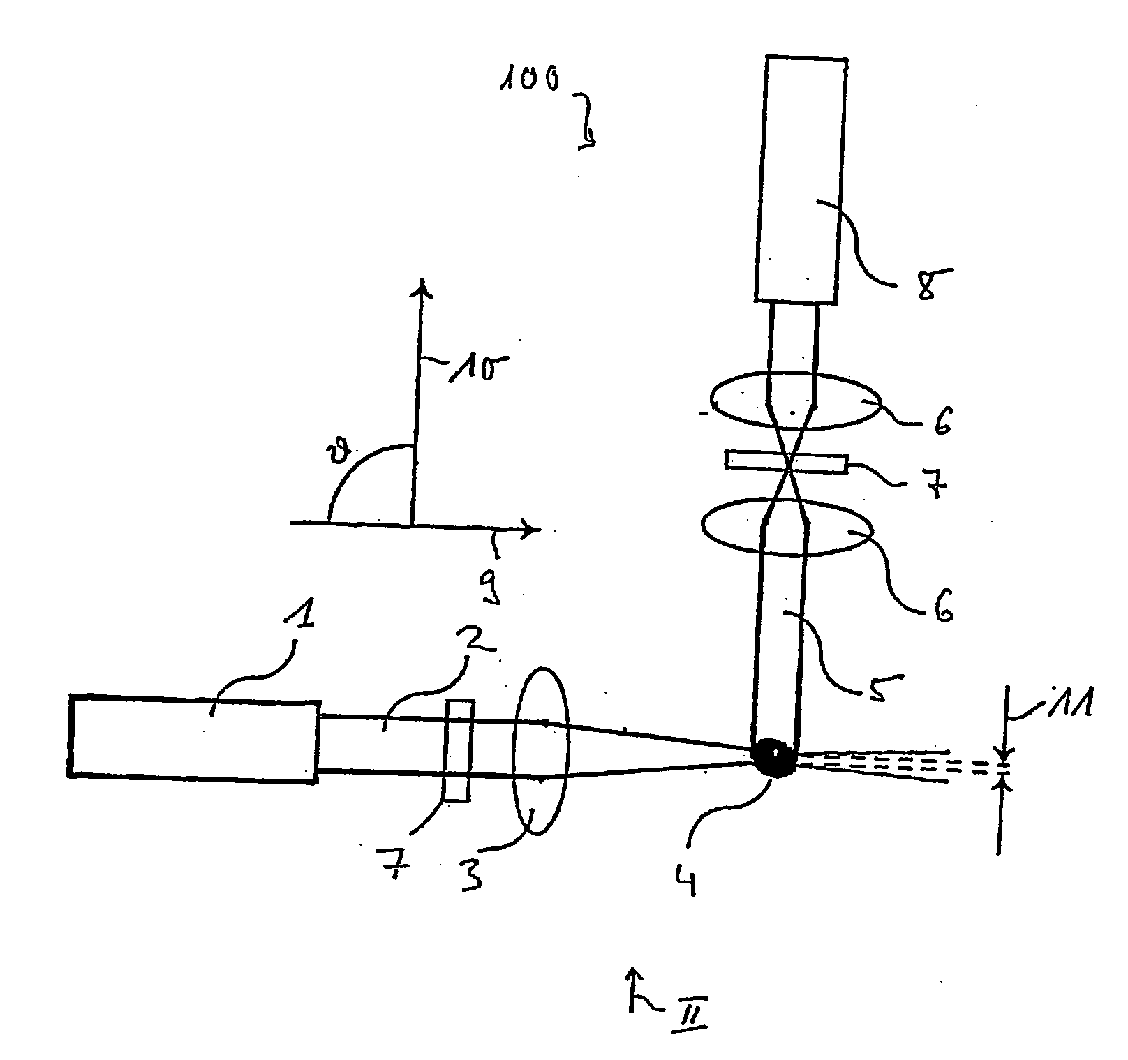
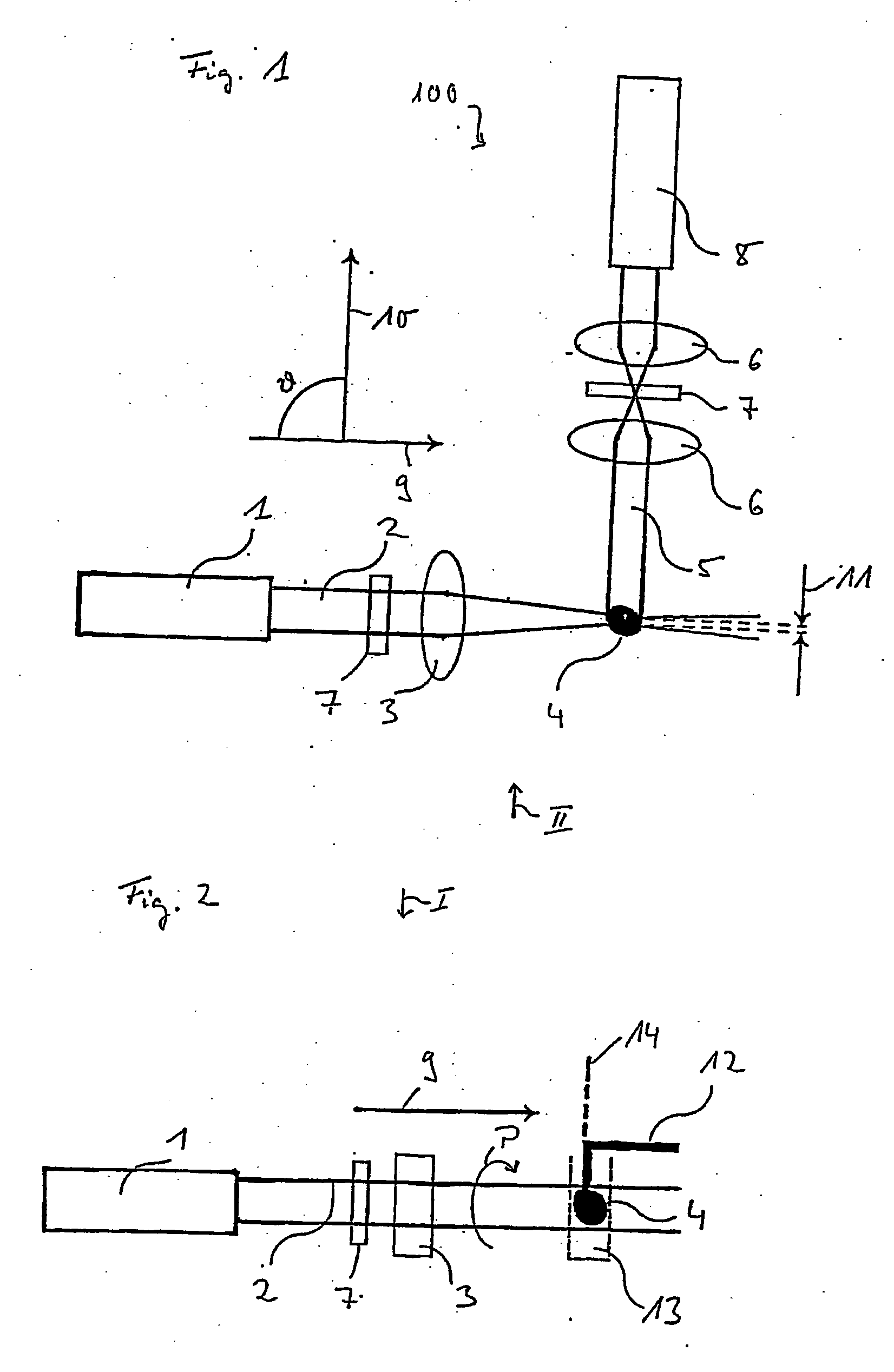
[0058]FIG. 1 shows an embodiment of a microscope 100 according to the invention. The embodiment comprises a light source 1, a collimated light beam 2 from which is focused into a sample 4 by a cylindrical lens 3. The cylindrical lens 3 creates a thin vertical light strip 11 by which fluorescent emission can be induced in the sample 4. Fluorescent light in a detection beam path 5 is projected through detection optics 6 onto a two-dimensional detector 8. The two dimensional detector 8 can be, for example, a CCD camera.

[0059] The structure is particularly simple owing to the substantially right-angled arrangement (=90 degrees) of an illumination direction 9 and a detection direction 10. In particular, the use of dichroic mirrors for separating illumination light from the light source and fluorescent light from the sample 4 in the detection beam path 5 can be obviated. Filters 7 in the illumination beam path 2 and in the detection beam path 5 are glass filters or acousto- / electro- / magn...


PUM


Abstract

The invention relates to a microscope in which a layer of the sample is illuminated by a plurality of thin strips of light (11) passed through a grid (34) and the sample is viewed (5) perpendicular to the plane of the strips of light. To record the image, the object (4) is displaced through the strips of light (11). At least three different images of the objects (4) are made at different phase angles. The images can be combined to form a single combined image.

Description

REFERENCE TO PREVIOUS APPLICATIONS [0001] This application is a Continuation-in-Part of Ser. No. 10 / 538,081.FIELD OF THE INVENTION [0002] The present invention relates to a microscope suitable for the high resolution, three-dimensional viewing of millimeter-sized biological objects. BACKGROUND TO THE INVENTION [0003] In contrast to work on single cells, light microscopy studies on embryos and other samples relevant to developmental biology suffer from the particular problems of absorption and resolution loss. For example, biological questions relating to gene expression patterns in developing organisms can currently be answered only with difficulty by light microscopy imaging methods, since they are often too slow, too weakly resolving or technically complex, or they do not allow millimeter-size objects to be viewed with a sufficiently high free working distance or inside a sample holder. An acceptable solution must allow the handling of large samples and rapid high-resolution acqui...

Claims


Application Information

Patent Timeline
IPC IPC(8): G02B21/06
CPCG02B21/06G02B21/0032G02B21/0076G01N21/6458G02B21/367G01N21/4795G02B21/16G02B21/0048G02B21/0056G02B21/26
Inventor STELZER, ERNST H.K.
Owner EURO LAB FUER MOLEKULARBIOLOGIE EMBL
Why Eureka
Try Eureka