Communication system and communication method using the same

a communication system and communication method technology, applied in the field of communication systems and communication methods using the same, can solve the problems of difficult implementation of a phase modulator used by a sender, and achieve the effects of preserving security, and reducing the cryptographic key generation ra

Inactive Publication Date: 2007-05-17
JAPAN SCI & TECH CORP +2
View PDF24 Cites 18 Cited by
  • Summary
  • Abstract
  • Description
  • Claims
  • Application Information

AI Technical Summary

Benefits of technology

[0014] In a quantum cryptographic device disclosed in the above-cited Patent Document 2, to make an interferometer for temporally splitting an optical pulse and an interferometer for recombining the temporally split optical pulses the same, the sender needs to rotate the polarization directions of the optical pulses by exactly 90 degrees. If the polarization rotation angle deviates from 90 degrees, the optical pulses passing through the same path in the first station (i.e., a receiver) while going and returning increase. The increase of the optical pulses decreases not only interference visibility but also the cryptographic key generation rate.
[0017] An object of the present invention is to enable an accurate 90-degree polarization rotation at the second station (i.e., the transmitter) with a reversing configuration for preserving the security against the disturbance of the polarization state at the transmission path, without using the Faraday mirror which causes the decrease in the cryptographic key generation rate. In addition, an object of the present invention is to provide a communication system capable of employing a polarization-dependent phase modulator and a communication method using the same.

Problems solved by technology

A first disadvantage is that it is difficult to implement a phase modulator used by a sender.

Method used


Image

  • Communication system and communication method using the same
  • Communication system and communication method using the same
  • Communication system and communication method using the same

Examples


embodiments

[0051] Embodiments of the present invention will be described in detail with reference to the drawings.

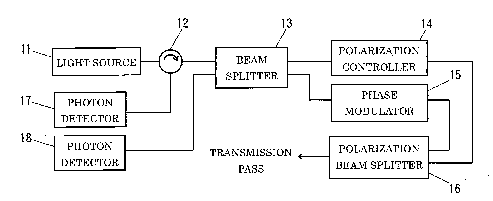
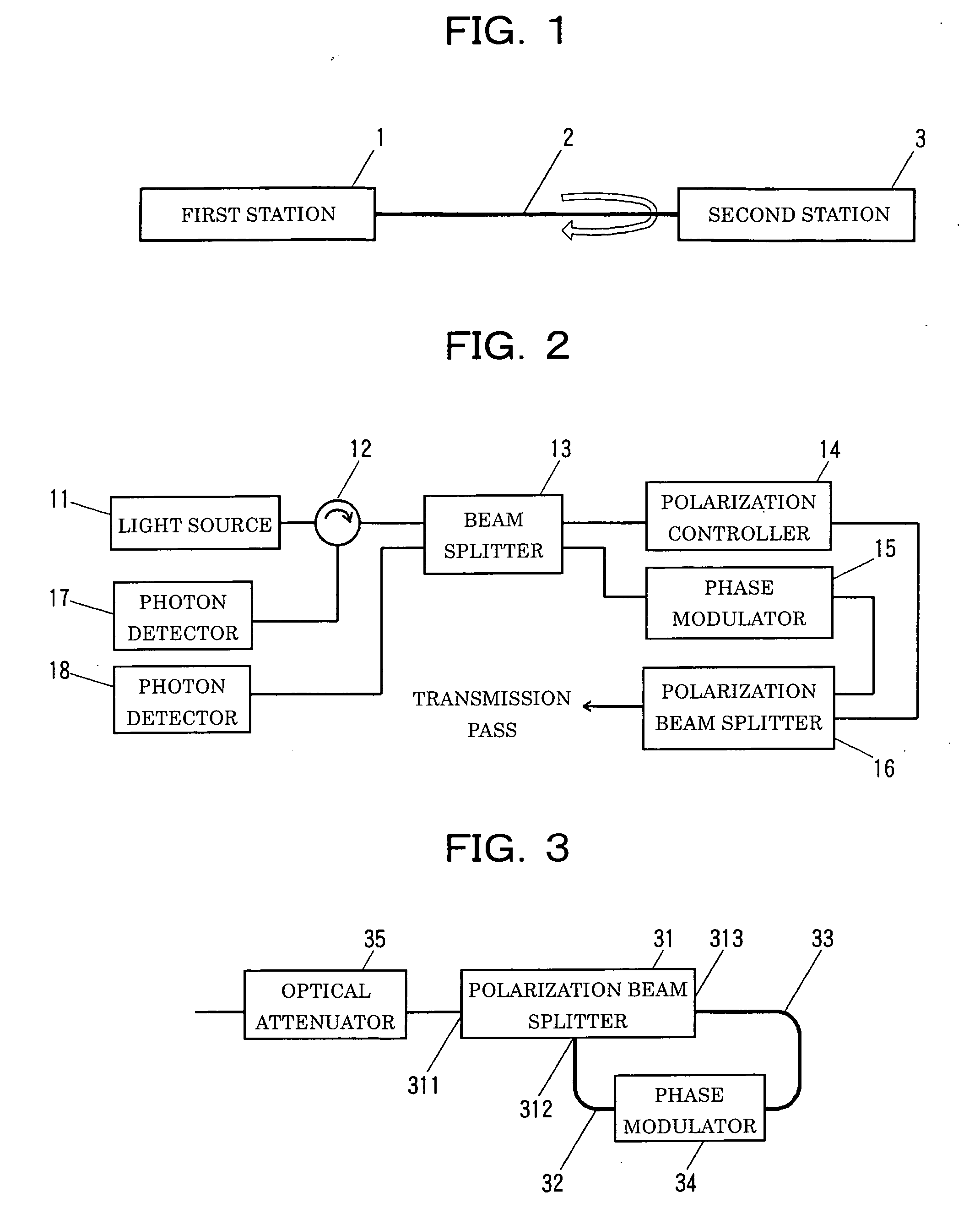
[0052]FIG. 1 is a schematic configuration diagram of a communication system (a quantum cryptography system) according to an embodiment of the present invention.

[0053] As shown in this figure, a quantum cryptography system of the present invention includes a first station (a receiver) 1, a transmission path 2, and a second station (a transmitter) 3. Optical pulses are emitted from the first station 1 into the transmission path 2, modulated at the second station 3, and returned into the transmission path 2. Then, bit values of the optical pulses are measured at the first station 1.

[0054] Accordingly, the first station 1 has means for emitting temporally divided optical pulses into the transmission path 2 and measuring a phase difference between the optical pulses returning from the transmission path 2.

[0055] After their polarization states are disturbed at the transmission path 2...


PUM


Abstract

A communication system capable of employing polarization-dependent phase modulators with a reversing configuration that preserves security against disturbance of a polarization state at a transmission path but without using Faraday mirrors and a communication method using the same are provided. A quantum cryptography system of the present invention includes a first station 1, a transmission path 2, and a second station 3. The first station 1 has means for emitting time-divided optical pulses into the transmission path 2 and measuring a phase difference between the optical pulses returning from the transmission path 2. The transmission path 2 is a medium of light. The second station 3 has means for reversing traveling directions of the optical pulses, means for producing a phase difference, corresponding to a random number bit value to be transmitted, between the time-divided optical pulses, means for splitting the entering optical pulse into orthogonally polarized components and producing a 180-degree phase difference therebetween, means for rotating each polarization direction by 90 degrees, means for eliminating a component resulting from a deviation from the polarization rotation angle of 90 degrees, and means for attenuating optical pulse intensity to include no more than 1 photon per bit.

Description

TECHNICAL FIELD [0001] The present invention relates to communication systems and communication methods using the same, in particular, to a communication system for performing a quantum cryptographic key distribution to share cryptographic keys through optical fiber communication and a communication method using the same. BACKGROUND ART [0002] In response to the recent explosive growth of the Internet and the practical application of electronic commerce, the social need for cryptographic techniques is rising in order to achieve communication confidentiality, prevent unauthorized alteration, and authenticate individuals. Currently, common key systems such as DES (Data Encryption Standard) encryption and public key systems such as RSA (Rivest Shamir Adleman) encryption are widely used. These systems are based on “computationally secure” schemes. Thus, existing encryption methods are always threatened by advances in computer hardware and decryption algorithms. A practical application o...

Claims


Application Information

Patent Timeline
Patent Type & Authority Applications(United States)
IPC IPC(8): H04K1/00G01J4/00G01B9/02G01J3/45H04B10/00H04B10/70H04B10/85H04L9/08H04L9/12
CPCH04L9/0858
Inventor TOMITA, AKIHISANAKAMURA, KAZUOTAJIMA, AKIOTANAKA, AKIHIRONANBU, YOSHIHIROSUZUKI, SHUUJITAKEUCHI, TAKESHIMAEDA, WAKAKOTAKAHASHI, SEIGO
Owner JAPAN SCI & TECH CORP
Why Eureka
Try Eureka