Image enhancement using anisotropic noise filtering

a filtering and noise technology, applied in image enhancement, image analysis, instruments, etc., can solve the problems of increasing uncertainty per voxel, multiple sources of noise, complicated imaging in mri and ct, etc., to improve diagnostic capability, reduce noise, smooth noisy homogenous areas

Active Publication Date: 2007-05-17
CANON MEDICAL SYST COPRPORATION
View PDF39 Cites 71 Cited by
  • Summary
  • Abstract
  • Description
  • Claims
  • Application Information

AI Technical Summary

Benefits of technology

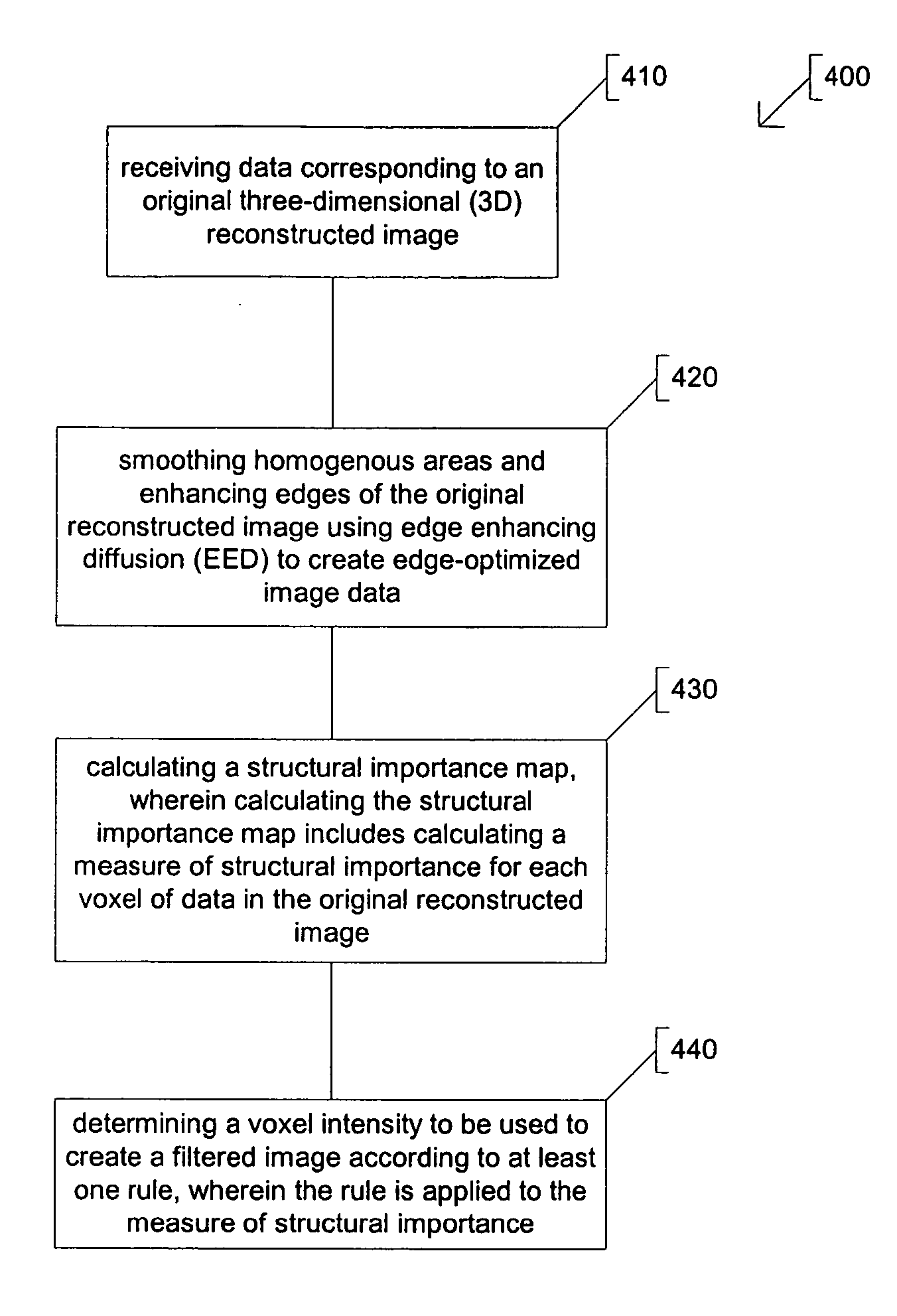
[0006] This document discusses, among other things, systems and methods for improving diagnostic capability in 3D reconstructed images by reducing noise. A system example includes a database memory and a processor in communication with the database memory. The database memory stores original reconstructed image data corresponding to an original 3D image. The processor includes an image filtering module that smoothes noisy homogenous areas and enhances edges of the original reconstructed image using edge enhancing diffusion (EED) to create edge-enhanced image data. The image filtering module also calculates a structural importance map that includes a measure of structural importance for each voxel of data in the original reconstructed image, and determines a voxel intensity to be used to create a filtered image according to at least one rule applied to the measure of structural importance.

Problems solved by technology

Imaging in MRI and CT is complicated by image noise in the resulting reconstructed images.
There are several sources of noise in MRI.
Likewise, the uncertainty per voxel will also increase if the radiation dose is lowered or if there is a higher attenuation of the X-ray beams.
While increasing radiation dose improves image quality, lowering the dose decreases the risk of possible harmful side effects in patients from ionizing radiation.
Currently, filtering methods that give the best results in image quality are those that use algorithms that are computationally complex and are not regarded as useful in clinical applications.
An inaccurate discrete approximation can, for example, result in blurring of edges and small structures in the image that is not described by the continuous equation.
Solving equation (9) by multiplication of the matrix A with the ordered image Uk is very expensive in computation time.
However, choosing a too large scale for the calculation of the gradients will cause a low response in areas with important intermediate structures and will blur these structures.
It is typically not possible with EED to choose one optimum scale for calculating the derivatives that both smoothes all noise in homogeneous areas and preserves the resolution while increasing the contrast of small structures.
Another problem with EED is that it causes an equal amount of diffusion in the two directions perpendicular to the gradient.
Also, a typical approach to implementing EED is computationally intensive and is usually not regarded as useful in clinical applications due to lengthy processing times.
Thus, the final filtered image will contain an amount of noise that is between the original image and the EED image.
Smaller scale steps results in a more accurate solution but adds to the computation time.
Thus, the final filtered image will contain an amount of noise that is somewhere between the original image and the EED image.
Because the anisotropic diffusion algorithm is time consuming, a low number of iterations is chosen, essentially choosing computing time over high accuracy.
However, a semi-implicit scheme is typically considered to be too expensive in computing time per iteration.
This is because a considerable amount of computation time would be spent marking active voxels.
Just as in the marking method, this results in the same decrease in the number of voxels marked in the active voxel mask over subsequent iterations but further decreases the processing time per iteration.

Method used


Image

  • Image enhancement using anisotropic noise filtering
  • Image enhancement using anisotropic noise filtering
  • Image enhancement using anisotropic noise filtering

Examples


Embodiment Construction

[0021] In the following detailed description, reference is made to the accompanying drawings which form a part hereof, and specific examples in which the invention may be practiced are shown by way of illustration. It is to be understood that other embodiments may be used and structural or logical changes may be made without departing from the scope of the present invention.

[0022] The functions or algorithms described herein are implemented in software or a combination of software and human implemented procedures in one example. The software comprises computer executable instructions stored on computer readable media such as memory or other type of storage devices. The term “computer readable media” is also used to represent carrier waves on which the software is transmitted. Further, such functions correspond to modules, which are software, hardware, firmware or any combination thereof. Multiple functions are performed in one or more modules as desired, and the embodiments describ...


PUM


Abstract

A method including receiving data corresponding to an original three-dimensional (3D) reconstructed image, smoothing homogenous areas and enhancing edges of the original reconstructed image using edge enhancing diffusion (EED) to create edge-enhanced image data, and calculating a structural importance map. The structural importance map includes a measure of structural importance for each voxel of data in the original reconstructed image. Voxel intensities to be used to create a filtered image are determined according to at least one rule applied to the measure of structural importance.

Description

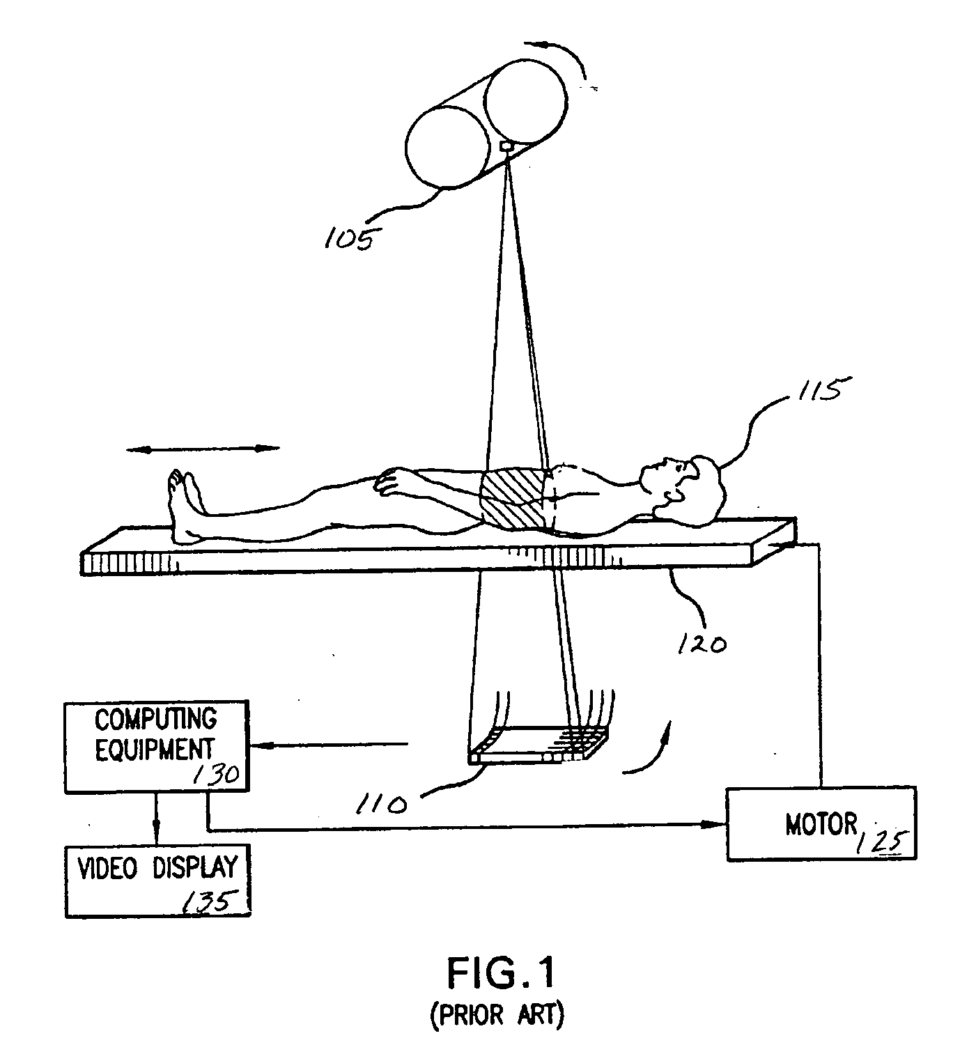
TECHNICAL FIELD [0001] The field generally relates to image processing and, in particular but not by way of limitation, to systems and methods to enhance reconstructed three dimensional (3D) diagnostic images. BACKGROUND [0002] Computer X-ray tomography (CT) is a 3D viewing technique for the diagnosis of internal diseases. FIG. 1 shows an example of a prior art CT system 100. The system includes an X-ray source 105 and an array of X-ray detectors 110. In CT, the X-Ray source is rotated around a subject 115 by a CT scanner. The X-ray source 105 projects radiation through the subject 115 onto the detectors 110 to collect projection data. The subject 115 may be placed on a movable platform 120 that is manipulated by a motor 125 and computing equipment 130. This allows the different images to be taken at different locations. The collected projection data is then transferred to the computing equipment 130. A 3D image is then reconstructed mathematically from the rotational X-ray projecti...

Claims


Application Information

Patent Timeline
Patent Type & Authority Applications(United States)
IPC IPC(8): G06K9/00G06K9/40G06V10/30
CPCG06K9/40G06T5/002G06T5/003G06T5/20G06T2200/04G06T2207/10081G06T2207/20012G06T2207/20036G06T2207/20192G06T2207/30004G06V10/30
Inventor SCHAAP, MICHIELZUIDERVELD, KAREL
Owner CANON MEDICAL SYST COPRPORATION
Why Eureka
Try Eureka