High Air Fraction Photonic Band Gap Fibers

a technology of photonic band gap and high air fraction, which is applied in the field of high air fraction nonsilicabased glass fibers, can solve the problems of difficult manufacturing of high air fraction preforms, weaker specialty oxide and non-oxide glasses, and difficult handling,

Inactive Publication Date: 2007-05-17
THE UNITED STATES OF AMERICA AS REPRESENTED BY THE SECRETARY OF THE NAVY
View PDF5 Cites 18 Cited by
  • Summary
  • Abstract
  • Description
  • Claims
  • Application Information

AI Technical Summary

Problems solved by technology

Irrespective of the technique used to make the preform, it is very difficult to make high air fraction preforms, especially from specialty glasses such as chalcogenides, halides, chalcohalides, and the like.
Unlike silica, which is a relatively strong material, specialty oxide and non-oxide glasses may be weaker and become difficult to fabricate, and moreover, difficult to handle when the air fraction is so high.

Method used


Image

  • High Air Fraction Photonic Band Gap Fibers
  • High Air Fraction Photonic Band Gap Fibers
  • High Air Fraction Photonic Band Gap Fibers

Examples


example 1

[0032] Single tube—A single glass tube made from As39S61 glass was drawn to a fiber under 2.8 in H2O gas pressure inside the tube. The ratio of the hole diameter to the outer diameter of the tube was increased considerably in the fiber by increasing the pressure in the hole during drawing. The air fraction was increased from 32% to 85% in this example. It can be even larger (>90%) depending upon the viscosity, temperature, draw rate, and pressure. The uniformity and concentricity was not compromised by this process.

example 2

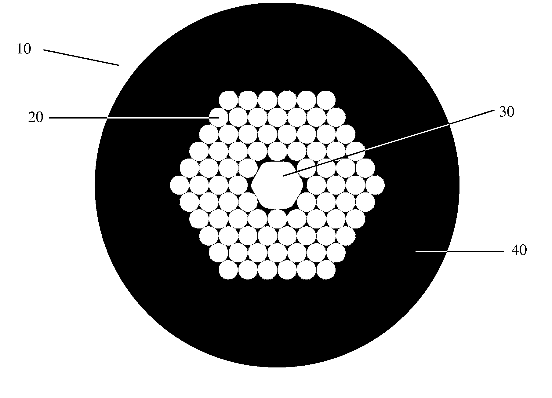
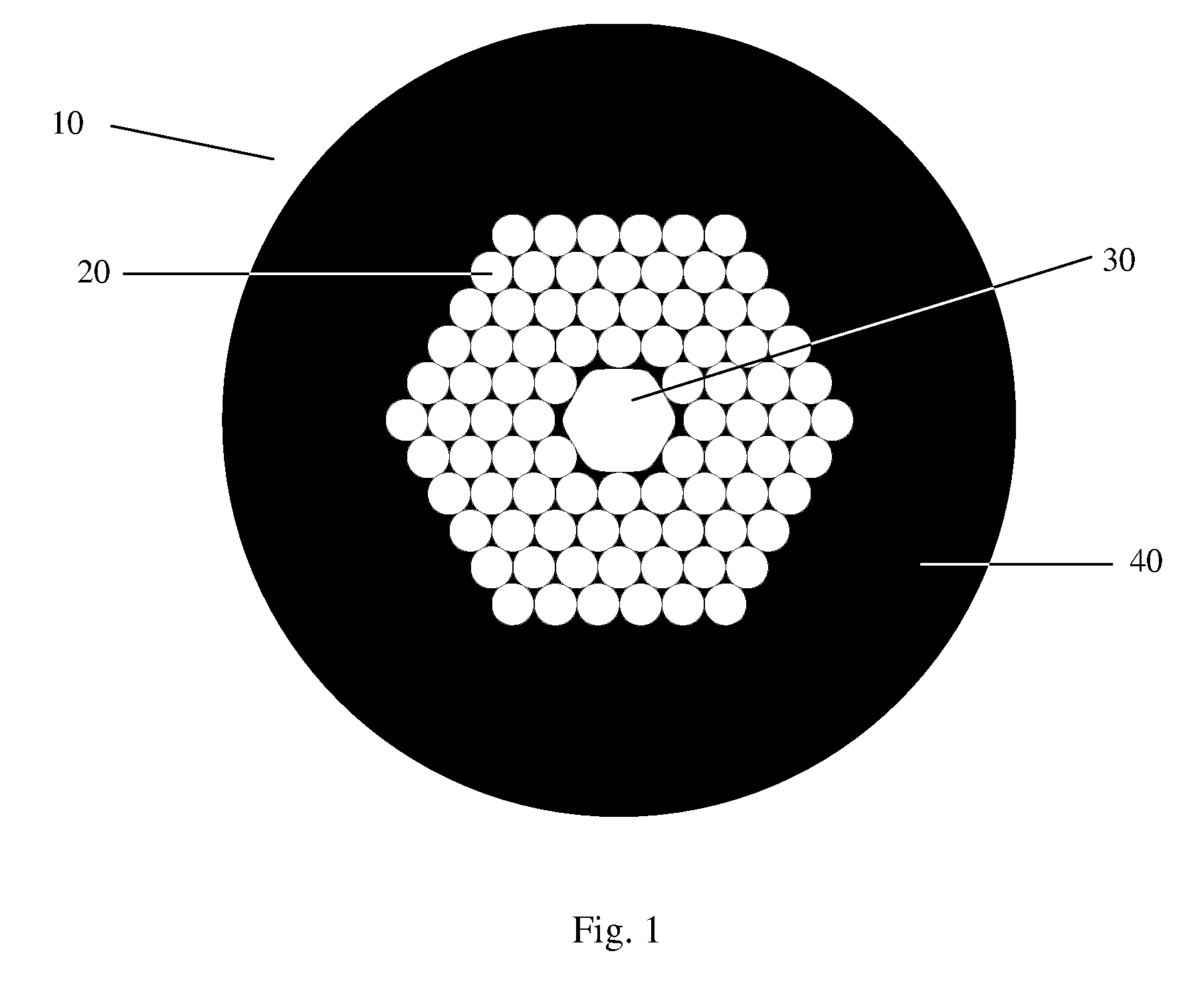
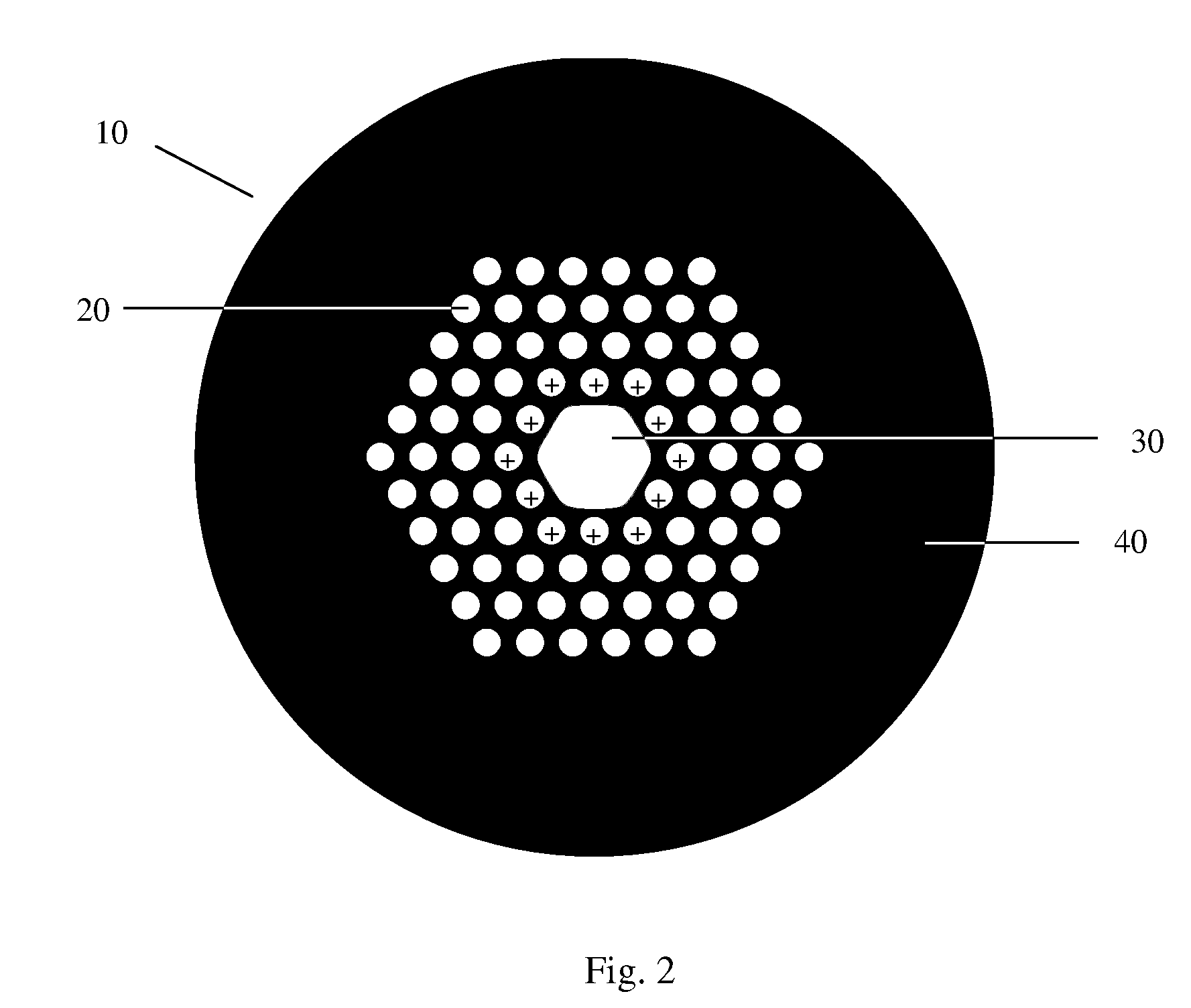
[0033] Preform—This example pertains to a microstructured preform made from As39S61 glass having a large central opening and 12 surrounding openings in a single hexagonal configuration (3 openings per edge of the hexagon). The preform was placed on the fiber draw tower and attached to gas pressurizing assembly. The preform was heated up to 310° C when it softened and fiber drawing was initiated. The pressure above the microstructured preform was changed and this caused changes to the hole diameters. The central core was open to the atmosphere. Increasing the pressure increased the hole size and therefore air fraction in the fiber. For example, without gas pressure, the microholes in the fiber were about 6 μm in diameter. However, the application of a nitrogen gas pressure equivalent to 2 in H2O increased the micro-hole diameter to about 23 μm. The initial size of the microholes in the preform was about 1 mm diameter. This preform did not possess an optimized photonic band gap struct...

example 3

[0034] Increased gas pressure—This example shows how the air fraction of a microstructured preform, containing several layers of holes, can be increased by using gas pressure applied uniformly to the central opening and surrounding openings during fiber drawing. The glass was As39S6and the air fill fraction of the microstructured region of the preform was 74%. FIGS. 4(a)-(c) show pictures of microstructured fibers that were drawn using different pressures. FIG. 4(a) was generated with no gas pressure and resulted in an air fill fraction of 47%. FIG. 4(b) was generated with 1 in H2O of N2 in both the microstructured region and the central opening, and resulted in an air fill fraction of 58%. Pressure of 2 and 3 in H2O of N2 resulted in air fill fractions of 67% and 69% respectively. FIG. 4(c) was generated with 4 in H2O of N2 and resulted in an air fill fraction of 78%. It is clearly evident that increasing the pressure to 4 in H2O increased the air fraction as noted by the thinner w...


PUM

PropertyMeasurementUnit
diameteraaaaaaaaaa
wavelength regionaaaaaaaaaa
viscosityaaaaaaaaaa

Abstract

A photonic band gap fiber and method of making thereof is provided. The fiber is made of a non-silica-based glass and has a longitudinal central opening, a microstructured region having a plurality of longitudinal surrounding openings, and a jacket. The air fill fraction of the microstructured region is at least about 40%. The fiber may be made by drawing a preform into a fiber, while applying gas pressure to the microstructured region. The air fill fraction of the microstructured region is changed during the drawing.

Description

[0001] This application is a divisional of U.S. patent application Ser. No. 10 / 904,062, filed Oct. 21, 2004, which is a continuation-in-part application of U.S. patent application Ser. No. 10 / 632,210, filed on Aug. 1, 2003, now U.S. Pat. No. 6,993,230, which is incorporated herein by reference.BACKGROUND OF THE INVENTION [0002] 1. Field of the Invention [0003] The invention relates generally to high air-fraction non-silica-based glass fibers. [0004] 2. Description of the Prior Art [0005] Hollow core photonic band gap (HC-PBG) fibers have been fabricated from silica glass and reported in the literature (Cregan et al., “Single-mode photonic band gap guidance of light in air,” Science, 285(5433), 1537-1539 (1999); Barkou et al., “Silica-air photonic crystal fiber design that permits waveguiding by a true photonic bandgap effect,” Optics Letters, 24(1), 46-48 (1999); Venkataraman et al., “Low loss (13 dB / km) air core photonic band-gap fibre,” ECOC, Postdeadline Paper PD 1. 1, Sep., 2002...

Claims


Application Information

Patent Timeline
Patent Type & Authority Applications(United States)
IPC IPC(8): G02B6/032B32B1/00C03B37/012C03C11/00C03C13/04G02BG02B6/02
CPCC03B37/0122C03B37/01274C03B37/025C03B37/02781C03B2201/60C03B2201/62C03B2201/70C03B2201/78C03B2201/80C03B2201/84C03B2201/86C03B2201/88C03B2203/12C03B2203/14C03B2203/16C03B2203/42C03B2205/10C03C11/00C03C13/043G02B6/02328G02B6/02347G02B6/02361G02B6/02371
Inventor SANGHERA, JASBINDER S.PUREZA, PABLO C.KUNG, FREDERIC H.GIBSON, DANIELSHAW, LESLIE BRANDONAGGARWAL, ISHWAR D.
Owner THE UNITED STATES OF AMERICA AS REPRESENTED BY THE SECRETARY OF THE NAVY
Why Eureka
Try Eureka