Reforming catalyst and method and apparatus for making and loading same

Active Publication Date: 2007-05-17
FUELCELL ENERGY INC
View PDF11 Cites 33 Cited by
  • Summary
  • Abstract
  • Description
  • Claims
  • Application Information

AI Technical Summary

Benefits of technology

[0009] In accordance with the embodiments of the invention described hereinafter, the above and other objectives are realized in a reforming catalyst member having an elongated body whose outer surface has a number of peak and valley regions so as to increase the area of the outer surface to enhance catalyst utilization. In the embodiments discl

Problems solved by technology

These techniques, however, are difficult to automate and are therefore not cost effective due to the small size of the catalyst particles.
Moreover, the catalyst placed in the anode current collector using these techniques often shifts or spills during assemb

Method used


Image

  • Reforming catalyst and method and apparatus for making and loading same
  • Reforming catalyst and method and apparatus for making and loading same
  • Reforming catalyst and method and apparatus for making and loading same

Examples


Embodiment Construction

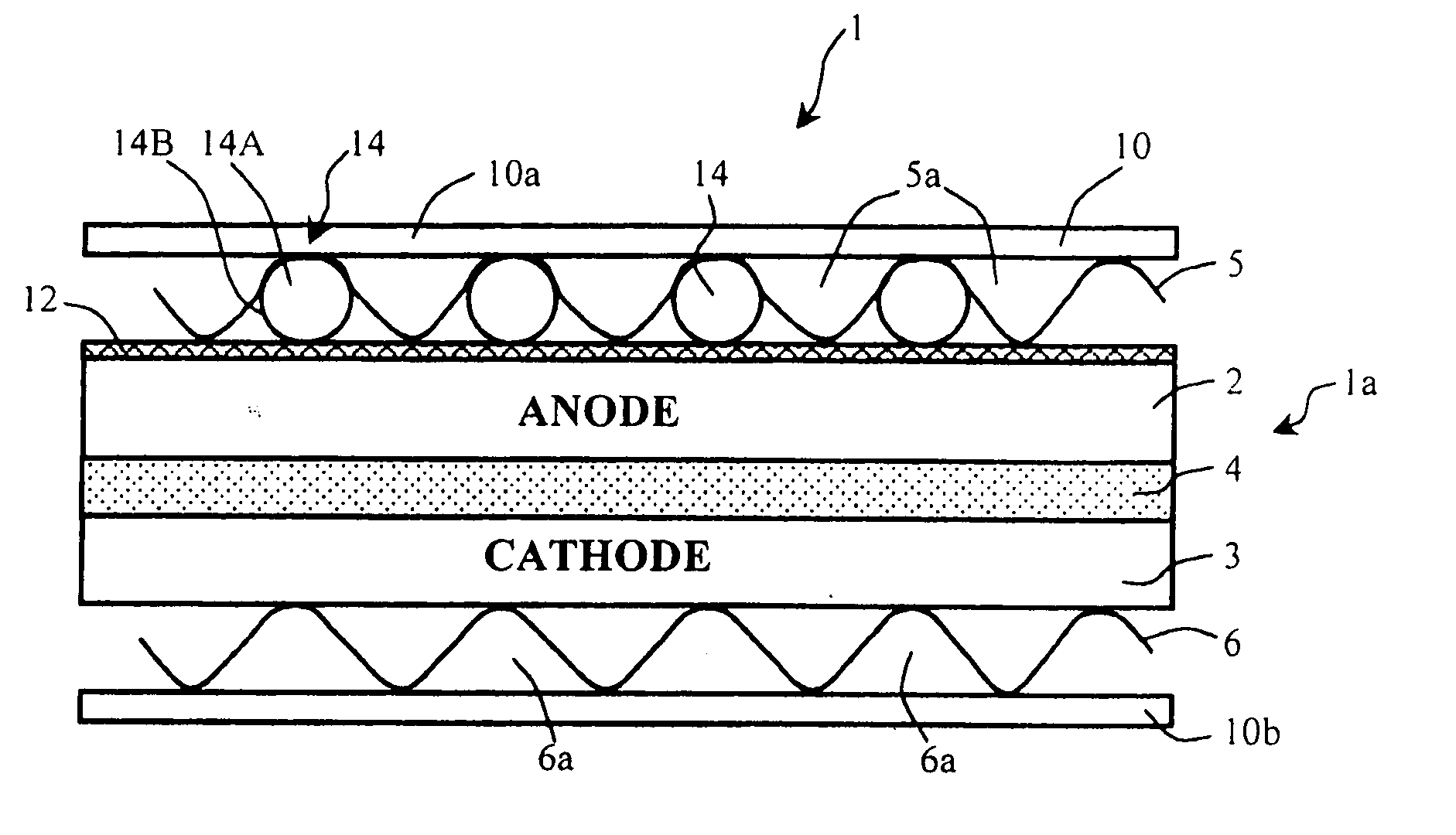
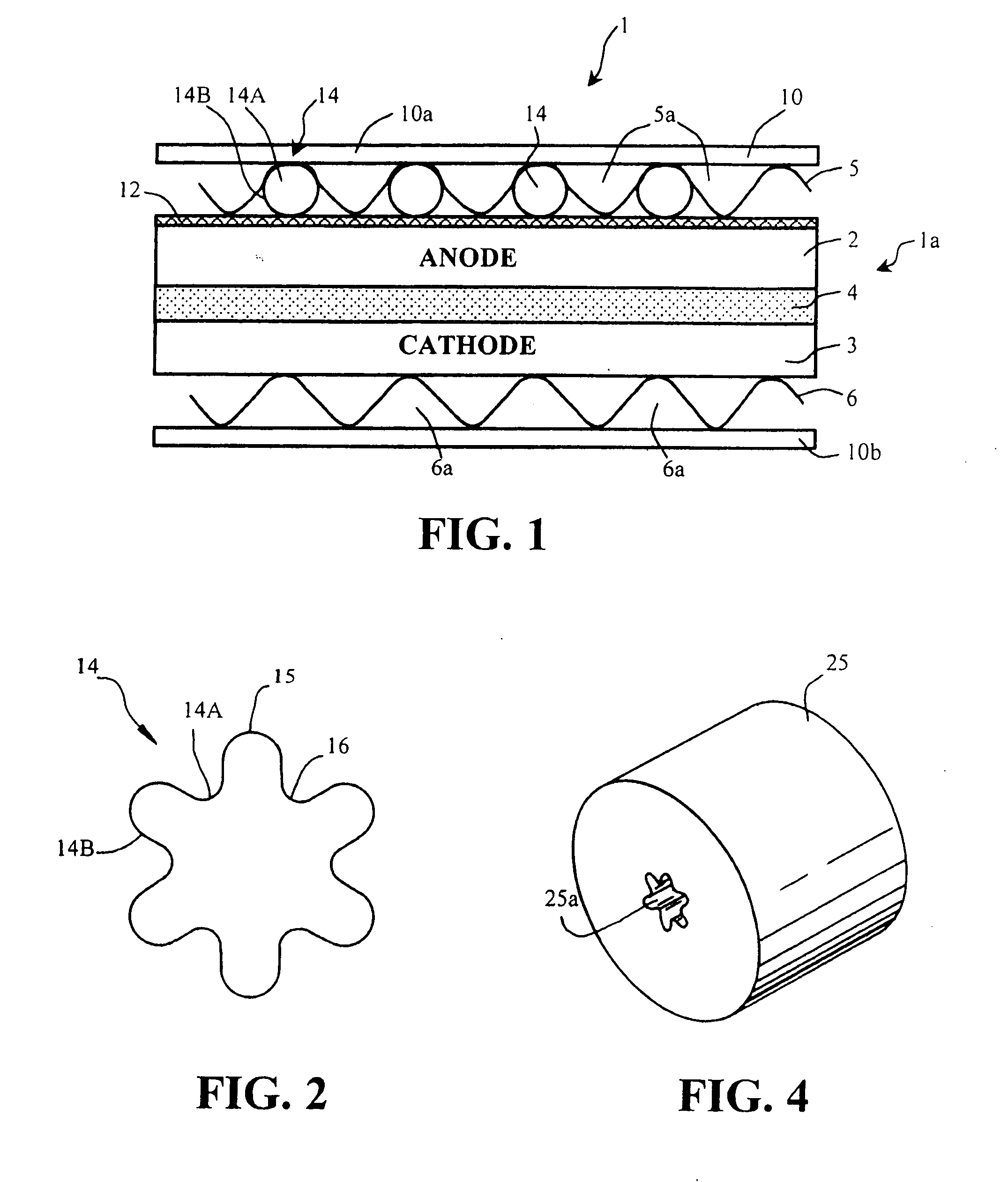
[0025]FIG. 1 shows a cross-sectional view of a portion of a fuel cell assembly 1. As shown, the fuel cell assembly 1 includes a fuel cell 1a comprising an anode electrode 2 and a cathode electrode 3 separated by an electrolyte matrix 4. The fuel cell 1a also includes an anode current collector 5 and a cathode current collector 6 which form gas passages 5a, 6a for fuel gas and oxidant gas, respectively. In the illustrative example shown in FIG. 1, the anode current collector 5 and the cathode current collector 6 are corrugated current collectors. The fuel cell assembly 1 also includes a plurality of bipolar separator plates 10 for separating adjacent fuel cells of the assembly from one another. In FIG. 1, the bipolar separator plate 10a separates the anode 2 and the anode current collector 5 of the fuel cell 1a from a fuel cell adjacent the anode side of the cell 1a, while the bipolar separator plate 10b separates the cathode 3 and the cathode current collector 6 of the cell 1a from ...


PUM

PropertyMeasurementUnit
Fractionaaaaaaaaaa
Fractionaaaaaaaaaa
Fractionaaaaaaaaaa

Abstract

A reforming catalyst member having an elongated body whose outer surface has a number of peak and valley regions so as to increase the area of the outer surface to enhance catalyst utilization.

Description

BACKGROUND OF THE INVENTION [0001] This invention relates to fuel cells and, in particular, to a reforming catalyst for use with such fuel cells. [0002] A fuel cell is a device which directly converts chemical energy stored in hydrocarbon fuel into electrical energy by means of an electrochemical reaction. Generally, a fuel cell comprises an anode and a cathode separated by an electrolyte, which serves to conduct electrically charged ions. In order to produce a useful power level, a number of individual fuel cells are stacked in series with an electrically conductive separator plate between each cell. [0003] In internally reforming fuel cells, a reforming catalyst is placed within the fuel cell stack to allow direct use of hydrocarbon fuels such as methane, coal gas, etc. without the need for expensive and complex reforming equipment. In a reforming reaction, fuel cell produced water and heat are used by the reforming reaction, and the fuel is internally reformed to produce hydrogen...

Claims


Application Information

Patent Timeline
IPC IPC(8): H01M8/06H01M4/86
CPCB01J23/755Y10T156/1039B01J35/04B01J35/1061B01J37/0009B01J37/344C01B3/40C01B2203/0233C01B2203/067C01B2203/1058C01B2203/1241C01B2203/16H01M4/8885H01M8/0254H01M8/0291H01M8/0637H01M2008/147Y02E60/50Y02E60/526B01J35/026H01M8/0289Y02P20/52Y02P70/50H01M4/86H01M4/88H01M8/04
Inventor KATIKANENI, SAI P.CORREA, SALVADOR E.GLADKE, EDWARD H.
Owner FUELCELL ENERGY INC
Why Eureka
Try Eureka