
Measurement system and method for use in determining the patient's condition

a measurement system and patient technology, applied in the field of optical measurement system and method, can solve the problems of loss of hearing, pain, feeling of fullness and pain, etc., and achieve the effects of improving transmission quality, simple construction, and simple us

Inactive Publication Date: 2007-05-17
CHAMELEON MEDICAL INNOVATION
View PDF11 Cites 127 Cited by
  • Summary
  • Abstract
  • Description
  • Claims
  • Application Information

AI Technical Summary

Benefits of technology

[0029] The normalized reflectivity spectrum can be further normalized by a certain wavelength λ0 within the selected spectrum range, such that all the light intensities are measured relative to the intensity at wavelength λ0. Hence, the effect of parameter C can be eliminated. This can be implemented by setting a relative spectrum r(λ)=R(λ) / R(λ0) so that r(λ0)=1. The selected value of λ0 is the center of the wavelength range of the predetermined incident light.
[0033] Additionally, the technique of the present invention allows for conducting qualitative measurements at the same time as allowing the user (physician) to observe the target tissue itself. This is implemented by configuring the measuring unit (an optical probe) for transmitting light emanating from a target tissue (region of interest) along at least two separate optical channels. The probe comprises a probe head and a speculum member removably fitted to a distal end of the probe head. The probe head comprises light transmission means for directing an illuminating light to said target tissue via a distal end of the speculum, and means for directing light emanating from the target tissue along at least two separate optical channels. The speculum member is adapted for positioning the distal end thereof proximate to the target tissue. The distal end of the speculum member comprises an optical aperture for enabling illuminating light and emanating light to pass therethrough from and to the optical probe. The at least two separate optical channels comprise a first channel for enabling qualitative analysis of said light emanating from said target tissue, and a second channel for enabling quantitative analysis of said light emanating from said target tissue.
[0038] The present invention thus provides an improved optical probe which enables qualitative measurements to be taken in parallel to enabling observation of the tissue. The probe improves the quality of transmission therethrough of the light reflected or refracted by the tissues. The probe is relatively simple in construction and simple to use, and is relatively inexpensive to manufacture.

Problems solved by technology

When the fluid occurs, there usually is hearing loss, and there may be a feeling of fullness and pain.

Method used


Image

  • Measurement system and method for use in determining the patient's condition
  • Measurement system and method for use in determining the patient's condition
  • Measurement system and method for use in determining the patient's condition

Examples


Embodiment Construction

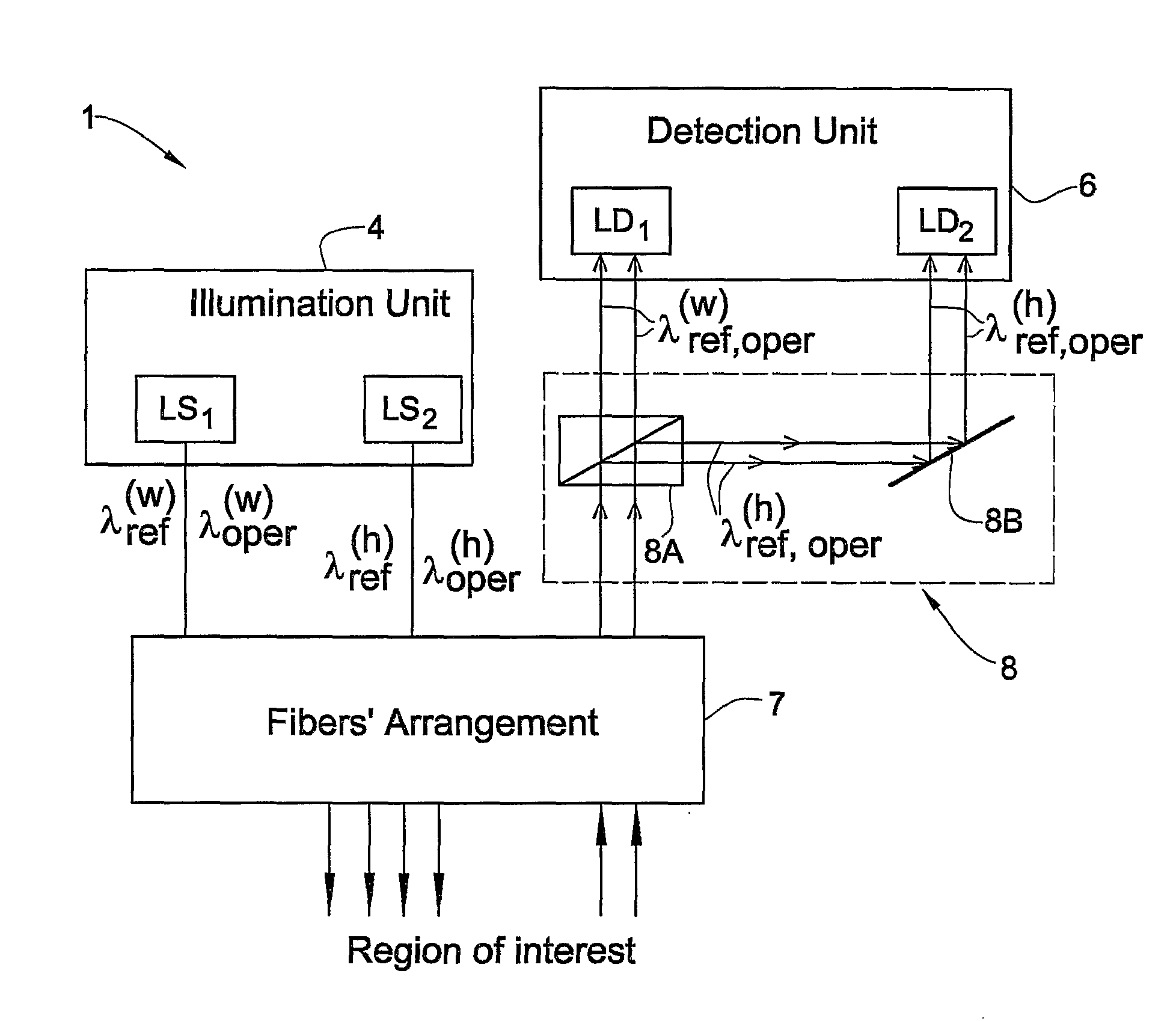
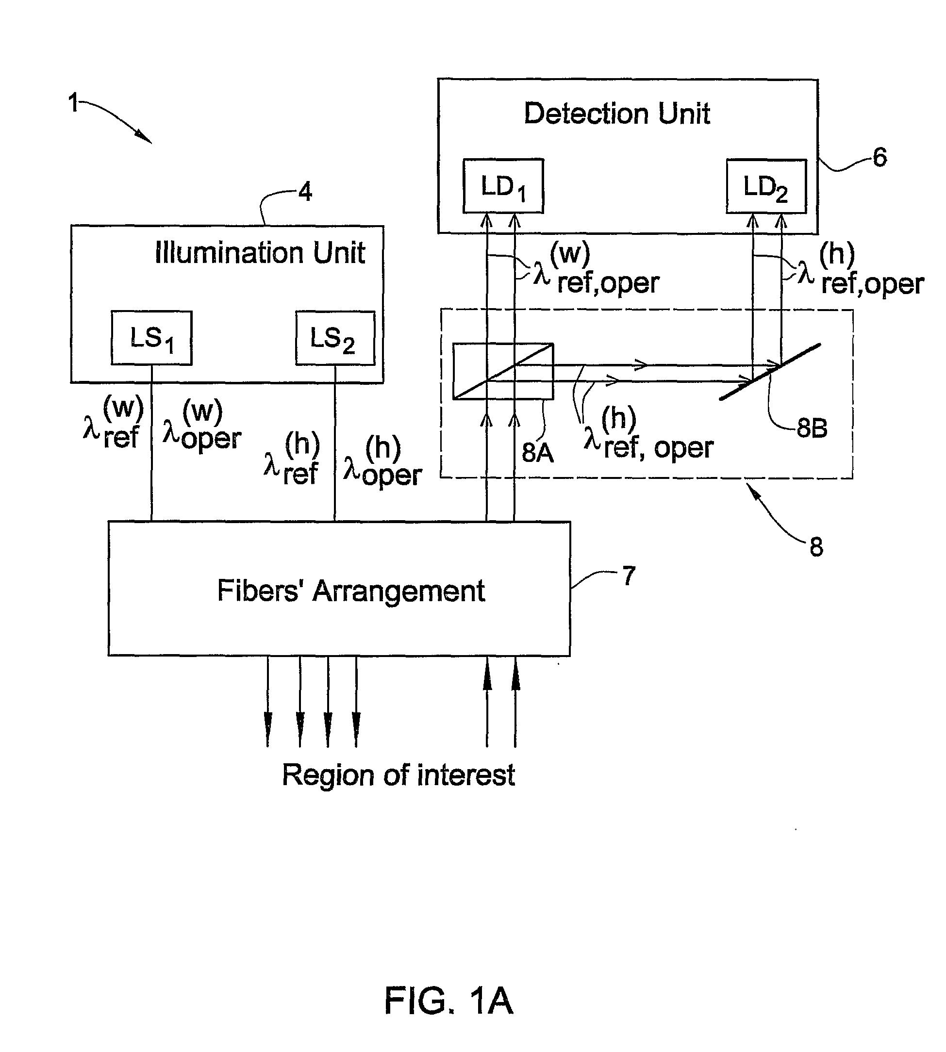
[0068] The present invention in its one aspect relates to an optical probe for measuring in a patient's ear. FIG. 1A is a block diagram of an optical probe 1 configured as an otoscope. The probe 1 includes an illumination unit 4 having one or more light sources—two light sources LS1 and LS2 in the present example; a detection unit 6 having one or more light detectors—two light detectors LD1, and LD2 in the present example; and a light directing assembly 7 including one or more optical fibers—six fibers in the present example. Also optionally provided in the light directing assembly is a filtering unit 8 accommodated in the optical path of light emerging from the fibers and propagating towards the detectors and configured for separating between light portions of different wavelengths. The filtering unit 8 includes one or more spectral filters (e.g., dichroic beam splitter, grating, resonator filter). In the present example, the filtering unit 8 includes a dichroic mirror 8A, and also...


PUM


Abstract

A measurement system and method are presented for use in detecting a predetermined condition of a patient's ear indicative of a certain disease such as SOM and SOM. The system comprises an optical measuring unit and a control unit connectable to the output of the measuring unit. The optical measuring unit is configured and operable for irradiating a region of interest in a patient's ear with incident light including at least two different wavelengths, detecting light responses of the region of interest to said at least two different wavelengths, and producing measured data indicative thereof. The at least two different wavelengths are selected such that the light response of the region of interest to at least one first wavelength is substantially independent of said predetermined condition and the light response to at least one second wavelength is affected by said predetermined condition. The control unit is operable for receiving and processing the measured data to generate output data indicative of the measurement results. The control unit is configured and operable for controlling operation of the optical measuring unit, and for receiving the measured data and processing it to generate output data indicative of whether or not said predetermined condition exists. The control unit comprises a memory utility for storing predetermined reference data indicative of the light response of the region of interest while in a healthy condition of a patient's ear; a data processing and analyzing utility preprogrammed for processing and analyzing the measured data by determining a relation between the measured light responses and the corresponding reference data.

Description

FIELD OF THE INVENTION [0001] This invention relates to an optical measurement system and method, as well as an optical probe to be utilized in such system, for use in determining the patient's condition, particularly the ear condition. BACKGROUND OF THE INVENTION [0002] Non-invasive optical measurements on a patient's body have been developed and are disclosed for example in the following patent publications: U.S. Pat. No. 4,882,492; U.S. Pat. No. 5,001,556; U.S. Pat. No. 5,280,788; U.S. Pat. No. 5,379,764; U.S. Pat. No. 5,582,168; U.S. Pat. No. 6,230,044; U.S. Pat. No. 6,319,199; U.S. Pat. No. 6,379,920; and WO 99 / 66830. The technique suitable for the diagnosis of ear-related diseases, such as otitis media, is disclosed in WO 02 / 39874 assigned to the assignee of the present application. [0003] Optical measurements on the patient's ear employ an optical probe such as an otoscope, in which the ear canal is illuminated via a suitable light source. The physician can then view the imag...

Claims


Application Information

Patent Timeline
IPC IPC(8): A61B6/00A61B5/00A61B1/04A61B1/227A61B1/32G01N21/31G01N21/35
CPCA61B1/227A61B5/0075A61B5/0084A61B5/6817G01N21/314G01N21/359
Inventor ROGERS, STEVEN R.
Owner CHAMELEON MEDICAL INNOVATION
Learn More