Membrane separation process

a technology of membranes and separation processes, applied in separation processes, membranes, liquid degasification, etc., can solve the problems of high maintenance cost of vacuum pumps, difficulty in condensing permeate, and increased maintenance costs

Active Publication Date: 2007-05-24
EXXON RES & ENG CO
View PDF9 Cites 48 Cited by
  • Summary
  • Abstract
  • Description
  • Claims
  • Application Information

AI Technical Summary

Problems solved by technology

While effective, vacuum pumps are expensive to maintain and can lead to difficulty in condensing the permeate.
Moreover, the vacuum pump oil may become contaminated with permeate, thus requiring more maintenance.
And as a result of their generally low displacement, vacuum pumps are not typically useful in large separations systems.
While simpler

Method used


Image

  • Membrane separation process
  • Membrane separation process
  • Membrane separation process

Examples


Embodiment Construction

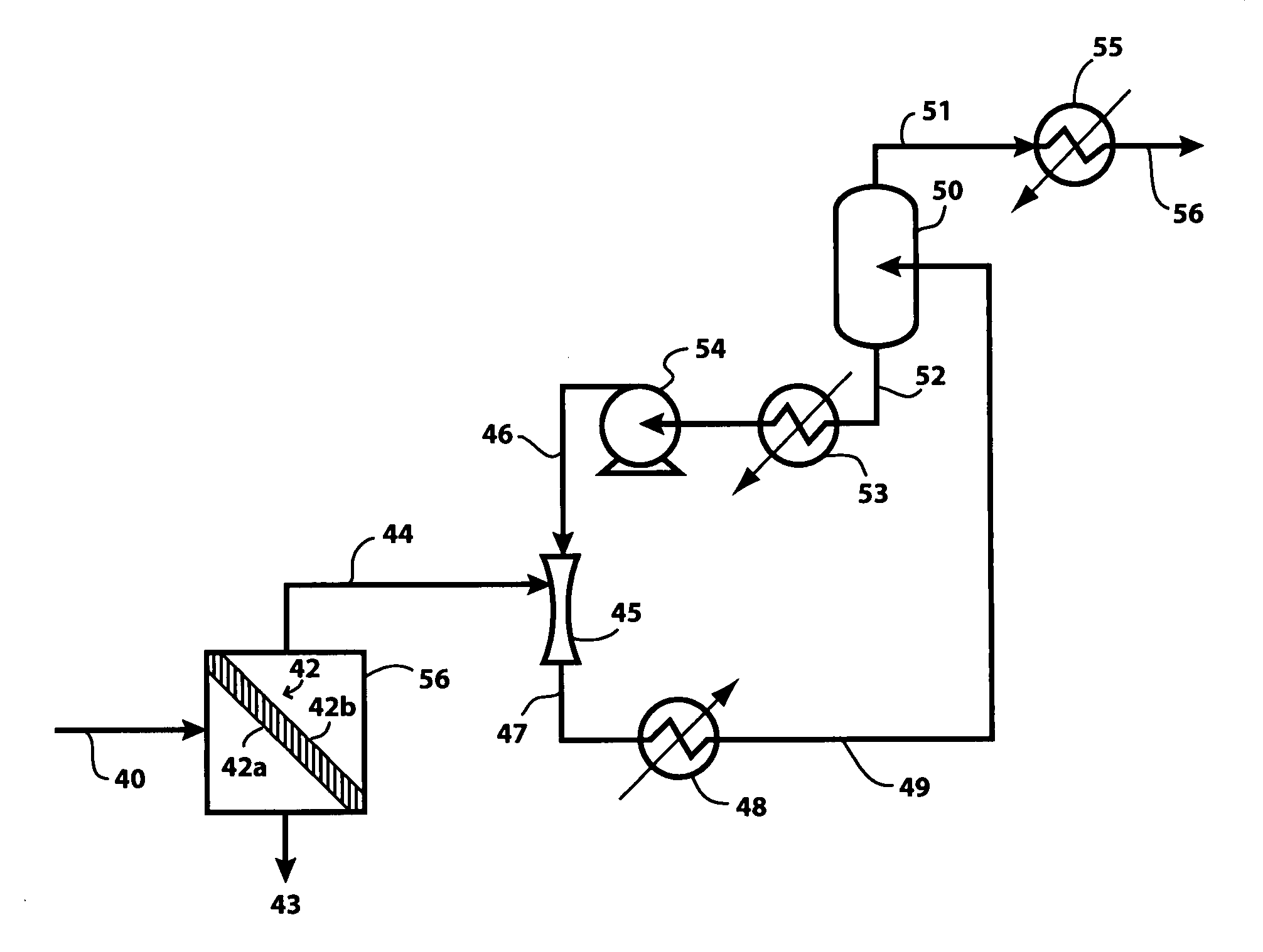
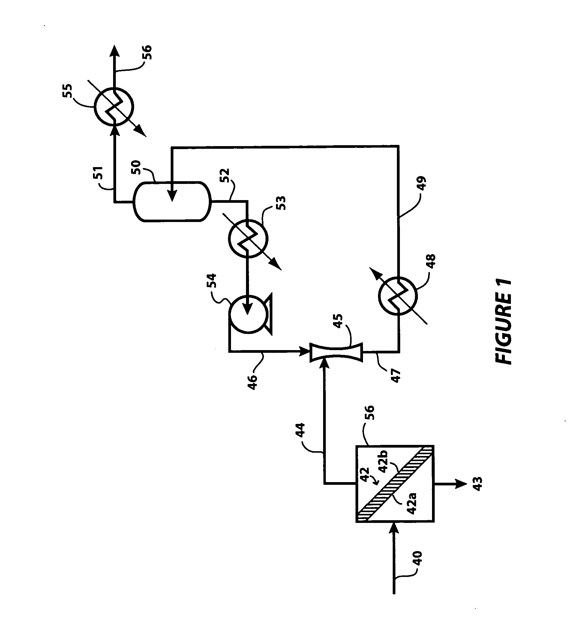
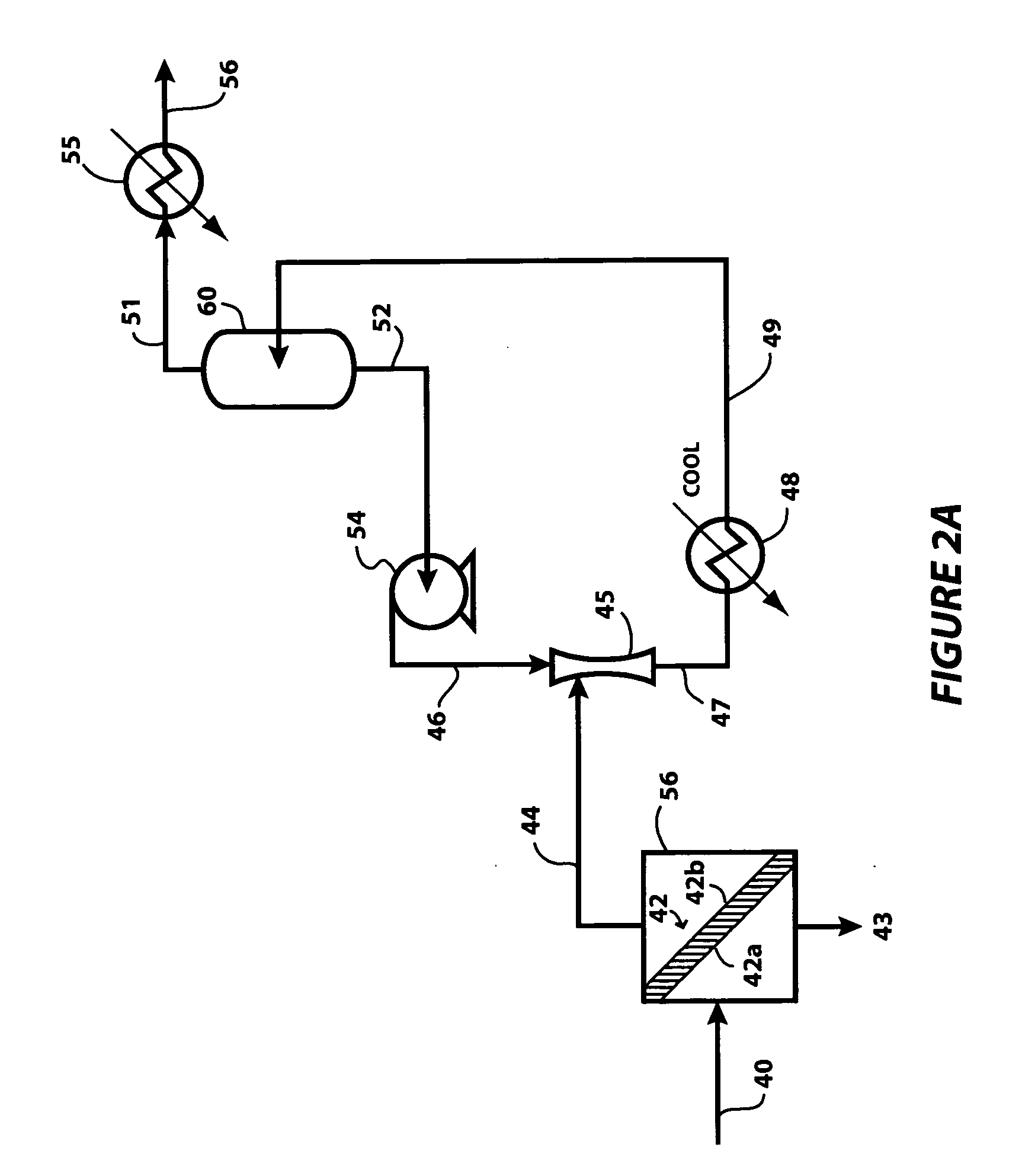
[0018] The present invention relates to a method for the separation of a multi-component feed stream into a permeate stream rich in one or more components of the feed stream and a distinct retentate stream lean in those same components. More particularly, the present invention is directed to an improved method of achieving the vacuum required on the permeate side of the membrane using an aspirator such as a Venturi-type nozzle (or “Venturi”) where the Venturi's working fluid has little or no affinity for the permeate. The invention can be understood by comparison to a conventional membrane separation process using a Venturi fluid that is immiscible with the permeate, as shown in FIG. 1.

[0019] In the conventional configuration shown in FIG. 1, the feed stream is pumped into a permeation unit 56 through line 40. The permeation unit contains a non-porous membrane 42 having a first surface 42a and an opposing second surface 42b. A portion of the feed dissolves into and permeates across...


PUM

PropertyMeasurementUnit
Temperatureaaaaaaaaaa
Boiling pointaaaaaaaaaa

Abstract

The invention relates to an improved membrane pervaporation and vapor permeation system in which the vacuum is produced by a fluid passing through a Venturi-type nozzle. The fluid is chosen from solvents that have little or no affinity for the permeate molecules. It is applicable over process feed rates, and can be used for the separation of aromatic species from hydrocarbon.

Description

FIELD OF THE INVENTION [0001] The present invention relates to a method for the separation of a multi-component feed stream into a permeate stream rich in one or more components of the feed stream and a retentate stream lean in those same components. BACKGROUND OF THE INVENTION [0002] Pervaporation is a separation process where a membrane in contact with a multi-component liquid feed selectively absorbs one or more of the species from the feed. The sorbed species permeate across the membrane under the influence of a concentration gradient that is produced by evaporating the sorbed molecules from the product side of the membrane using a vacuum or sweep gas. Permeate vapor is then condensed and recovered as a liquid. Vapor permeation differs from pervaporation in that the feed is already in the vapor phase. [0003] U.S. Pat. No. 5,753,008, incorporated by reference herein, discloses three ways for maintaining a sufficiently low partial pressure of permeate on the downstream side (also ...

Claims


Application Information

Patent Timeline
IPC IPC(8): B01D63/00
CPCB01D53/22B01D61/362B01D63/00B01D2313/22B01D2313/38C07B63/00C07C7/144C10G31/11B01D2313/221
Inventor SABOTTKE, CRAIG
Owner EXXON RES & ENG CO
Why Eureka
Try Eureka