
Electronic device with dual heat dissipating structures

a technology of heat dissipation structure and electronic device, which is applied in the direction of instruments, modifications by conduction heat transfer, and electrical apparatus casings/cabinets/drawers, etc., can solve the problems of large heat produced on both sides of the circuit board, limited space for disposing heat dissipation structures, and serious impact on function and the lifespan of power converters, so as to increase the volume of the electronic device. , the effect of increasing the heat dissip

Active Publication Date: 2007-05-24
DELTA ELECTRONICS INC
View PDF8 Cites 36 Cited by
  • Summary
  • Abstract
  • Description
  • Claims
  • Application Information

AI Technical Summary

Benefits of technology

[0007] An object of the present invention is to provide an electronic device with a major heat dissipating structure and an auxiliary heat dissipating structure disposed on the first and second heat producing surfaces of the electronic device respectively, wherein the first heat producing surface is located at a better heat dissipating surrounding relative to the second heat producing surface. Therefore the heat produced by the second heat producing surface can be conducted through the auxiliary heat dissipating structure and a connective portion to the major heat dissipating structure for assisting heat dissipation, so as to avoid the damage of the electronic elements caused by the heat accumulated near the second heat producing surface. Besides, the heat dissipation efficiency can be raised up without increasing the volume of the electronic device for catering to the miniaturization trend of the electronic device.

Problems solved by technology

Hence a lot of heat is produced on both sides of the circuit board while these electronic elements are working.
The stability of the electronic device depends on the heat dissipating efficiency thereof; however, for satisfying the circuit layout in a finite space, the space for disposing the heat dissipating structure is limited.
Nevertheless, if the heat produced by the high-power electronic elements on both sides of the circuit board cannot be dissipated efficiently, the function and the lifespan of the power converter will be seriously affected.
Furthermore, the overheated power converter might become out of order.
However, as the foregoing descriptions, with the trend of miniaturization of the electronic device, the space reserved for the heat sink is limited; hence the heat sink can be disposed only on one side of the double-layer circuit board or multi-layer circuit board of the power converter.
It is to be understood that the heat dissipation is hindered because of the air gap; therefore the electronic elements on the circuit board might be damaged owing to the heat accumulation.
The damaged electronic elements may affect the stability of the power converter and further cause the shutdown of the electronic system.
Moreover, no matter the active or passive cooling method is used in the electronic system, the heat accumulated in the air gap cannot be dissipated actively because the space for air flow is limited and thus a dead space for heat dissipation is formed.

Method used


Image

  • Electronic device with dual heat dissipating structures
  • Electronic device with dual heat dissipating structures
  • Electronic device with dual heat dissipating structures

Examples


Embodiment Construction

[0024] The present invention will now be described more specifically with reference to the following embodiments. It is to be noted that the following descriptions of preferred embodiments of this invention are presented herein for purpose of illustration and description only; it is not intended to be exhaustive or to be limited to the precise form disclosed.

[0025] The electronic device of the present invention is applied to an electronic system with a system circuit board, such as the power supply system of a liquid crystal display. The electronic device can be a power converter, preferably a DC / DC converter, but not limited thereto. In other words, any electronic device having a circuit board, both sides of which produce heat and need to be heat dissipated, can be included within the spirit of the present invention.

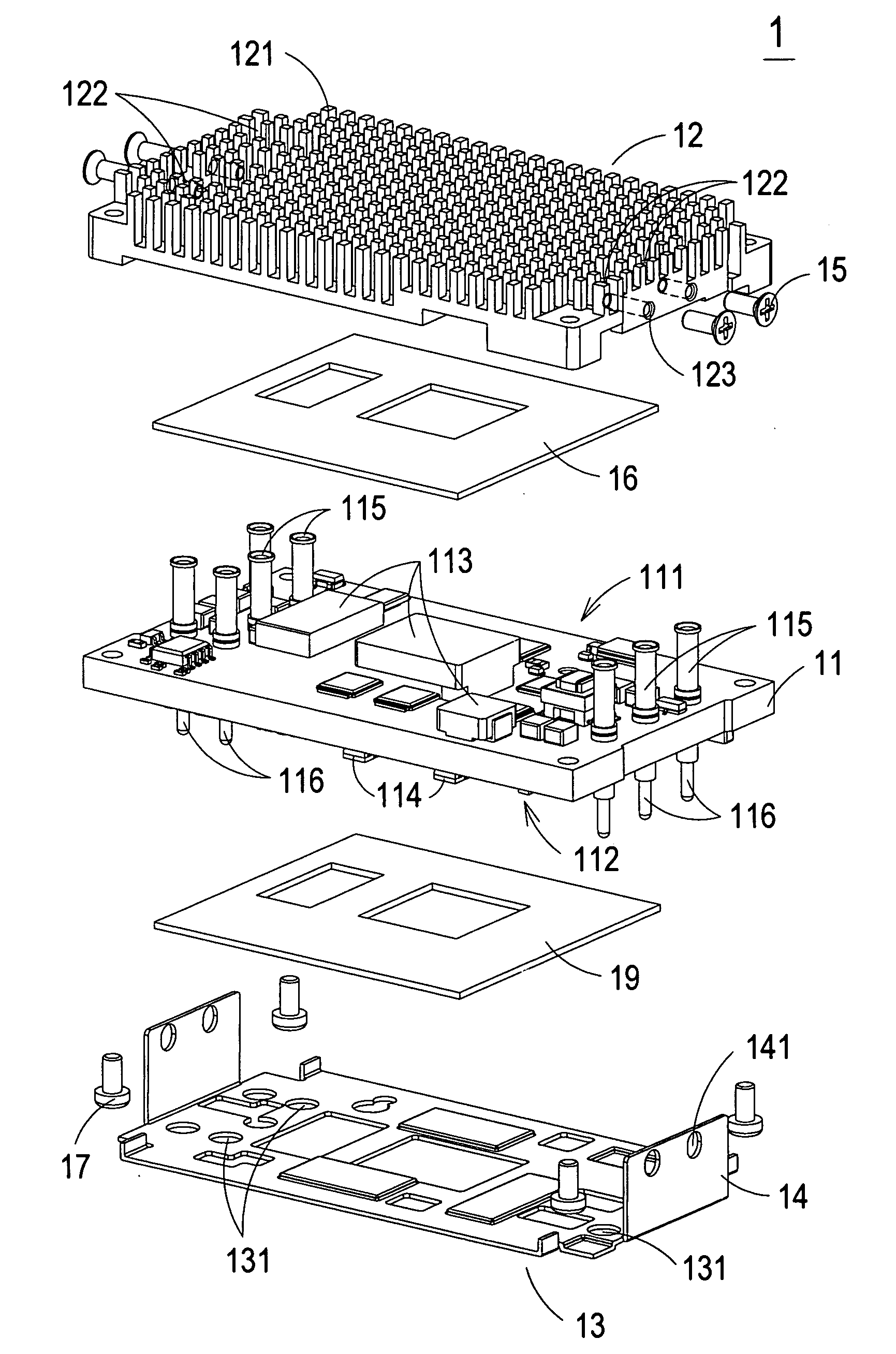
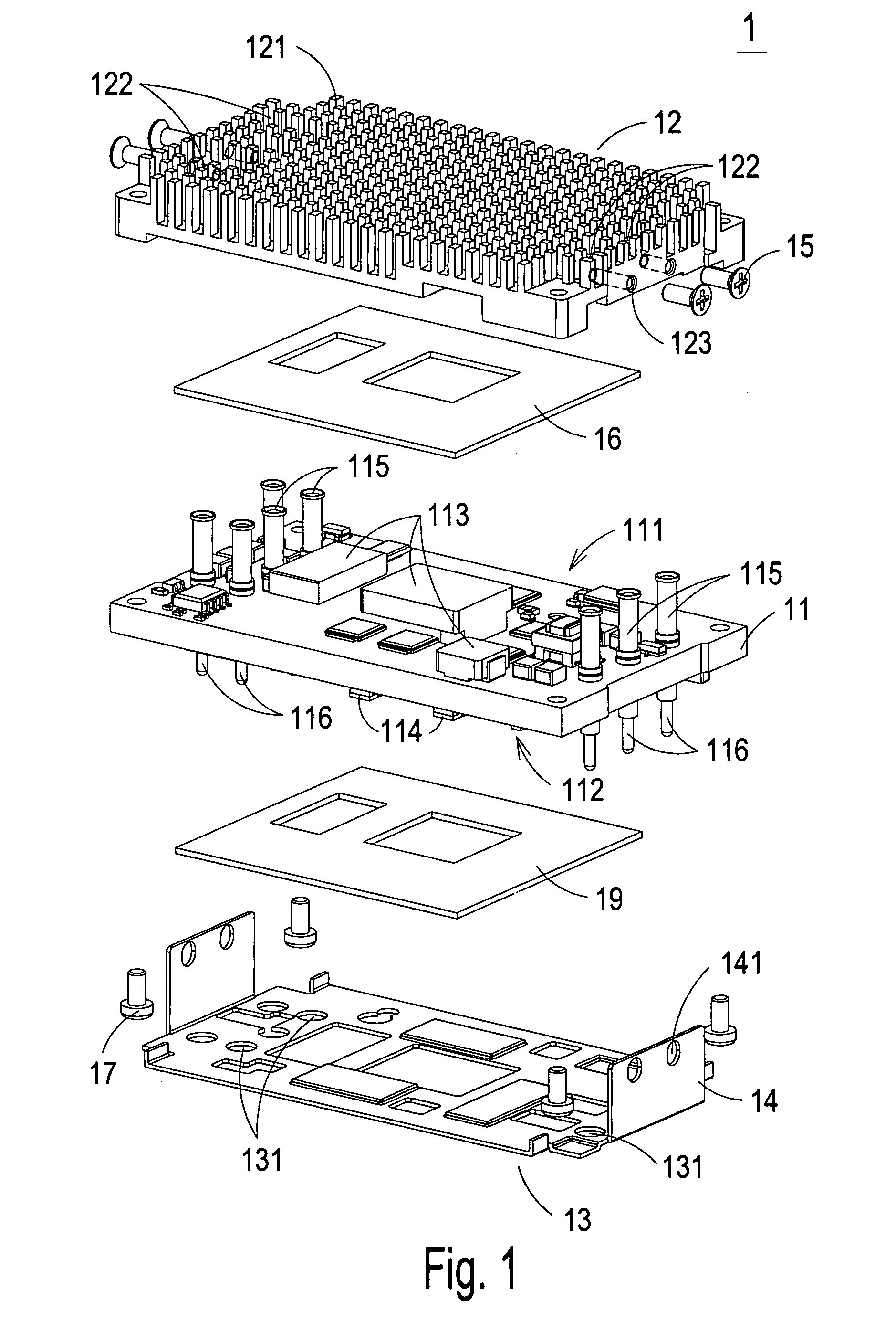
[0026] Please refer to FIG. 1, which is a schematic diagram showing the disassembled structure of the electronic device with dual heat dissipating structures accordin...


PUM


Abstract

An electronic device with dual heat dissipating structures use in an electronic system is disclosed. The electronic device comprises the circuit board having the first and second heat producing surfaces, the major and auxiliary heat dissipating structures disposed on the first and second heat producing surfaces of the circuit board respectively, and the connective portion connecting the auxiliary heat dissipating structure and the major heat dissipating structure. The second heat producing surface of the circuit board is a high-temperatured area relative to the first heat producing surface of the circuit board in the electronic system, thereby the heat produced by the second heat producing surface of the circuit board can be conducted to the major heat dissipating structure through the auxiliary heat dissipating structure and the connective portion for heat dissipation.

Description

FIELD OF THE INVENTION [0001] The present invention relates to an electronic device and more particularly to the electronic device with dual heat dissipating structures. BACKGROUND OF THE INVENTION [0002] With the progress of the technology, the driving efficiency of the electronic device is raised up. For increasing the driving power, accelerating the driving speed, and conforming to the trend of miniaturization, the volume of the electronic device is reduced and the design of the inner structure is compacted. Therefore the circuit board of the electronic device, such as the power converter, is designed as a double-layer circuit board or multi-layer circuit board, and the electronic elements are placed on both sides of the circuit board for saving space. [0003] Generally speaking, the electronic elements on the circuit board, such as capacitor, transistor, resistor, inductor, transformer, and diode, are high-power heat producing elements. Hence a lot of heat is produced on both sid...

Claims


Application Information

Patent Timeline
IPC IPC(8): H05K7/20
CPCH01L23/4006H05K7/20445H05K7/20509H01L2924/0002H01L2924/00
Inventor CHEN, TSU-CHENGHUANG, KAI-HUNGHSIEH, YI-HWA
Owner DELTA ELECTRONICS INC
Features
  • Generate Ideas
  • Intellectual Property
  • Life Sciences
  • Materials
  • Tech Scout
  • Unparalleled Data Quality
  • Higher Quality Content
  • 60% Fewer Hallucinations
Learn More