Illumination module

a technology of illumination module and illumination module, which is applied in the field of illumination module, can solve the problems of insufficient luminous efficacy, high cost, and difficult heat dissipation, and achieve the effect of reducing the volume of the illumination module and high power illumination

Inactive Publication Date: 2007-05-24
IND TECH RES INST
View PDF4 Cites 67 Cited by
  • Summary
  • Abstract
  • Description
  • Claims
  • Application Information

AI Technical Summary

Benefits of technology

[0013] In view of the disadvantages of prior art, the primary object of the present invention is to provide an illumination module having a plurality of light sources to be fitted in the periphery of the illumination module surrounding a reflecting member, which is opposite to those conventional illumination modules with light sources being arranged in the middle thereof while being surrounded by reflectors. Moreover, by using an optic software to calcul

Problems solved by technology

However, there are still shortcomings preventing LED lighting from being commercially popularized, that the shortcoming includes insufficient luminous efficacy, difficult to dissipate heat and high cost, etc.
Until recently, though, the price of an LED lighting system was too high for most residential use.
Nevertheless, with sales rising and more relating patents to be authorized, the price of high power LED illumination module is steadily decreasing.
However, an LED illumination module with high luminous flux output usually accompany with high power requirement that is going to cause the LED illumination module to operate in a high temperature ambient while the exhaust heat can not be effectively discharged from the LED chip.
If an LED illumination module is constantly operating in an environment of 120° C. or higher, the life span and luminous efficacy will be severely affected.
But the additional cooling device will affect the structural simplicity and reliability of the LED illumination module, and more particularly, it will increase the cost of the LED illumination module.
However, since the chip set 130 is limited to be disposed only on a pl

Method used


Image

  • Illumination module
  • Illumination module
  • Illumination module

Examples


Embodiment Construction

[0026] For your esteemed members of reviewing committee to further understand and recognize the fulfilled functions and structural characteristics of the invention, several preferable embodiments cooperating with detailed description are presented as the follows.

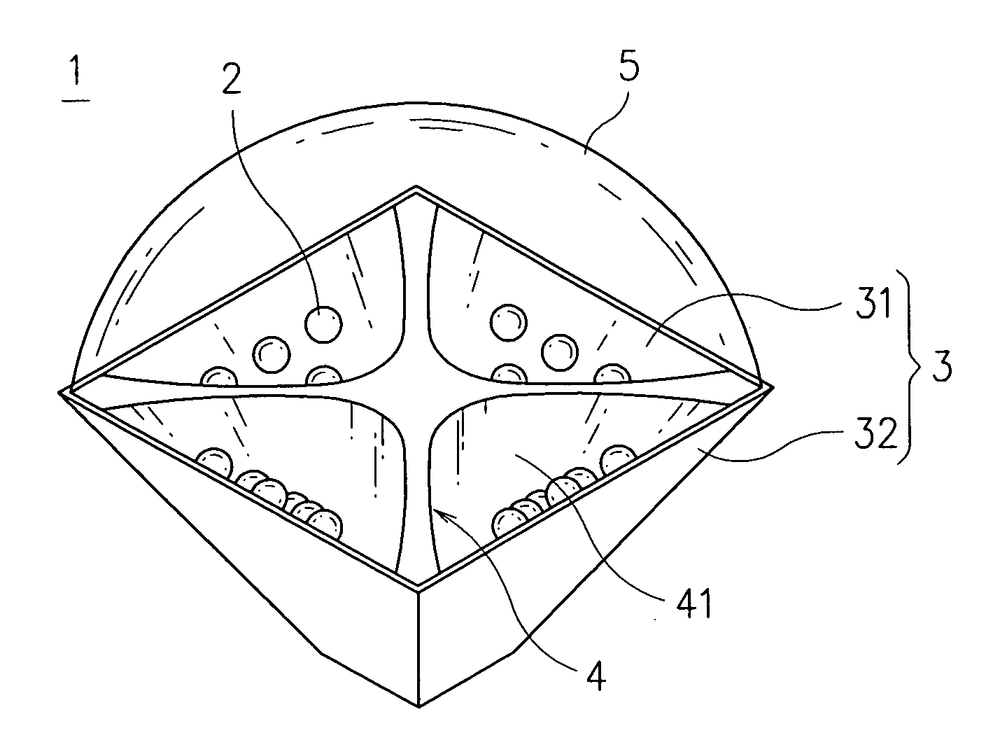
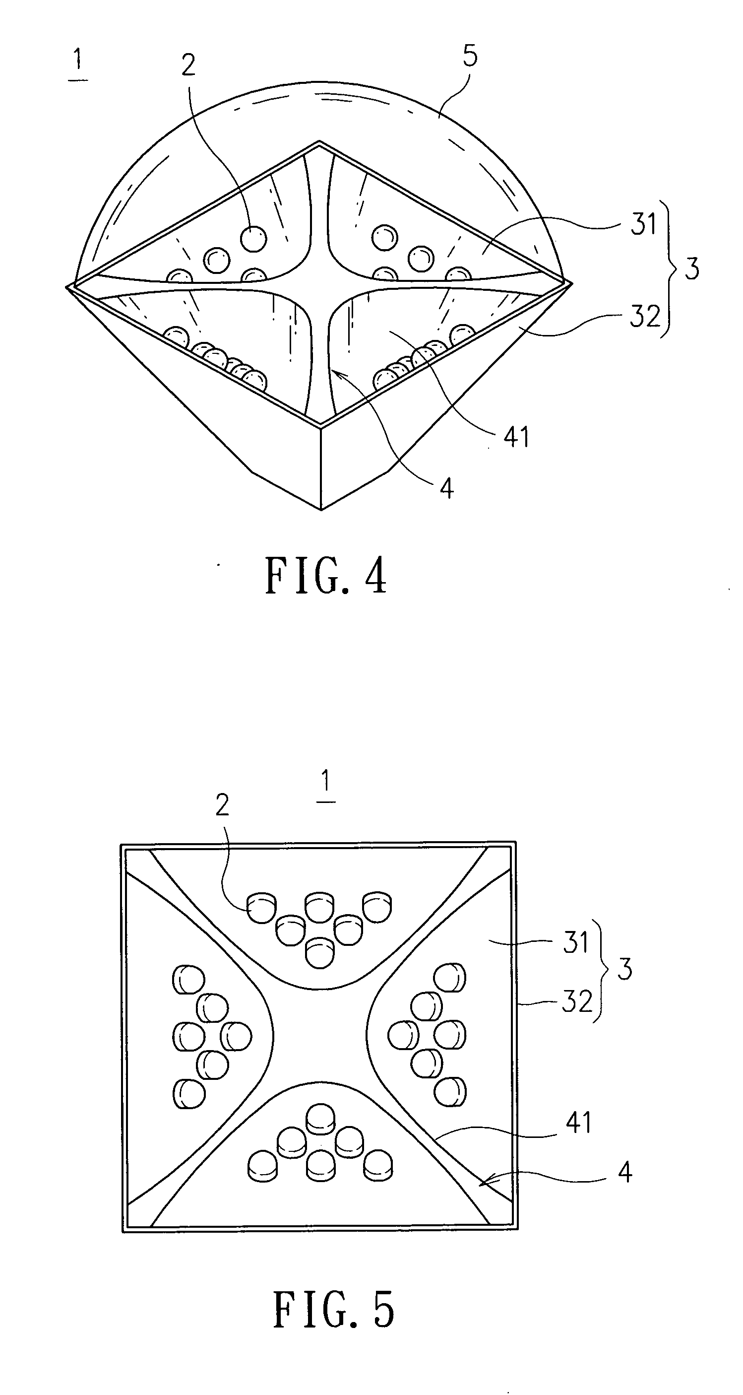
[0027] Please refer to FIG. 4 oFIG. 6, which are schematic diagrams illustrating an LED illumination module according to a preferred embodiment of the present invention. The illumination module 1 is comprises of a plurality of light sources 2, a plurality of light source substrates 3, a plurality of reflecting members 4 and a lens 5. any one of the plural light source 2 can be a device selected from the group consisting of an LED, a solid-state light source, an incandescent bulb, and a gas discharge lamp. The arrangement and the number of the light sources 2 are dependent on the size of the illumination module 1 and the type of light source 2 being selected. In this preferred embodiment, LEDs are selected as the light sourc...


PUM


Abstract

An illumination module is disclosed, which is comprised of a plurality of light sources, a plurality of light source substrates of high thermal conductivity, and a reflecting member for reflecting light. The plural light source substrates are arranged at positions corresponding to each other so as to form a polygon periphery of the illumination module, whereas the inner surface of the polygon periphery is enabled for at least one of the plural light sources to fit therein. The reflecting member is placed at the center of the module where it is corresponding to each of the plural light source substrates so as to reflect the light emitting from the light sources fitted thereon. In addition, a lens with light refraction ability is disposed at the light emitting end of the illumination module so as to enable the light illumination module to have light condensing/diffusing capability. Moreover, each light source substrate further comprises: a plurality of heat dissipating fins, being arranged at the outer surface thereof; and a assistant heat dissipating device; wherein the working range of the operation power and the luminous flux of the illumination module can be increased by the combined function provided by the heat dissipating fins and the assistant heat dissipating device. The assistant heat dissipating device can further comprise: a fan, being arranged at the bottom of the illumination module; and a heat pipe device, being fitted onto the light source substrate, for conducting waste heat to the heat dissipating fins to be dissipated.

Description

FIELD OF THE INVENTION [0001] The present invention relates to an illumination module, and more particularly, to a high power light emitting diode illumination module having a plurality of light sources to be fitted in the periphery of the illumination module surrounding a reflecting member, which is opposite to those conventional illumination modules with light sources being arranged in the middle thereof while being surrounded by reflectors. BACKGROUND OF THE INVENTION [0002] Light emitting diodes (LEDs) are semiconductor chips that convert electrical energy directly into light, which use much less power and last much longer than incandescent lights. Since LEDs are efficient, give off little heat, and can be embedded in plastic and other durable materials, they are becoming more and more popular and may be used increasingly in the future not only for a wide range of signal and sign applications, but also for illumination applications. Early versions of LED technology had very low ...

Claims


Application Information

Patent Timeline
IPC IPC(8): F21S19/00
CPCF21K9/00F21S48/1154F21S48/1159F21S48/325F21V5/04F21V29/02F21V29/83F21Y2101/02F21V29/677F21V29/74F21V29/773F21V29/78F21V29/006F21V29/67F21V29/51F21V29/76F21Y2115/10F21Y2107/40F21K9/68F21S41/143F21S41/147F21S45/49F21S45/43F21S41/153F21V29/763
Inventor CHOU, MING-CHIEHLIN, WEN-SHANCHIOU, YII-TAYCHU, CHUN-HSUN
Owner IND TECH RES INST
Why Eureka
Try Eureka