Spherical carbon nanostructure and method for producing spherical carbon nanostructures

Inactive Publication Date: 2007-05-24
CLEAN TECH INT
View PDF33 Cites 17 Cited by
  • Summary
  • Abstract
  • Description
  • Claims
  • Application Information

AI Technical Summary

Benefits of technology

[0012] The method may further include adding heat to the collection area with a heater element. For example, one or more heater elements such as electrical resistance heater elements may be included in the collection area, and operated to heat both the collection area and the collection surfaces provided in the collection area.
[0013] One preferred carbon nanostructure production process employs substantially pure liquid aluminum (99% aluminum by mass composition) at approximately 1650° F. as the reactant liquid. This reactant liquid has been found to liberate the desired carbon ions, and place these ions in the desired excited energy state for the production of carbon nanostructures. The process of producing carbon nanostructures may include heating the collection surfaces to between approximately 1350° F. and 1620° F. The process may also be performed without applying any heat to the collection surfaces other than heat from the reactant liquid and any heat released from the formation of carbon nanostructures. For example, the process of producing spherical carbon nanostructures may be performed with the temperature of the collection surfaces ranging from approximately 100° F. to 590° F. All of the spherical carbon nanostructures produced by the above-described preferred process have been produced without any nickel catalyst or other catalyst deposited on the col

Problems solved by technology

Despite the interest in carbon nanostructures and the potentially important uses for such structures, the practical application of carbon nanostructures in products has been slowed by the difficulty in manufacturing such structures.
The prior processes for producing or isolating carbon nanostructures have been found to produce only small quantities of carbon nanostructures and/or produce carbon nanostructures of inconsistent quality.
These impurities incorporated in the walls of the carbon nanostructures may have a negative impact on the qualities and properties of the nanostructure and may render it unsuitable for an intended

Method used


Image

  • Spherical carbon nanostructure and method for producing spherical carbon nanostructures
  • Spherical carbon nanostructure and method for producing spherical carbon nanostructures
  • Spherical carbon nanostructure and method for producing spherical carbon nanostructures

Examples


example 1

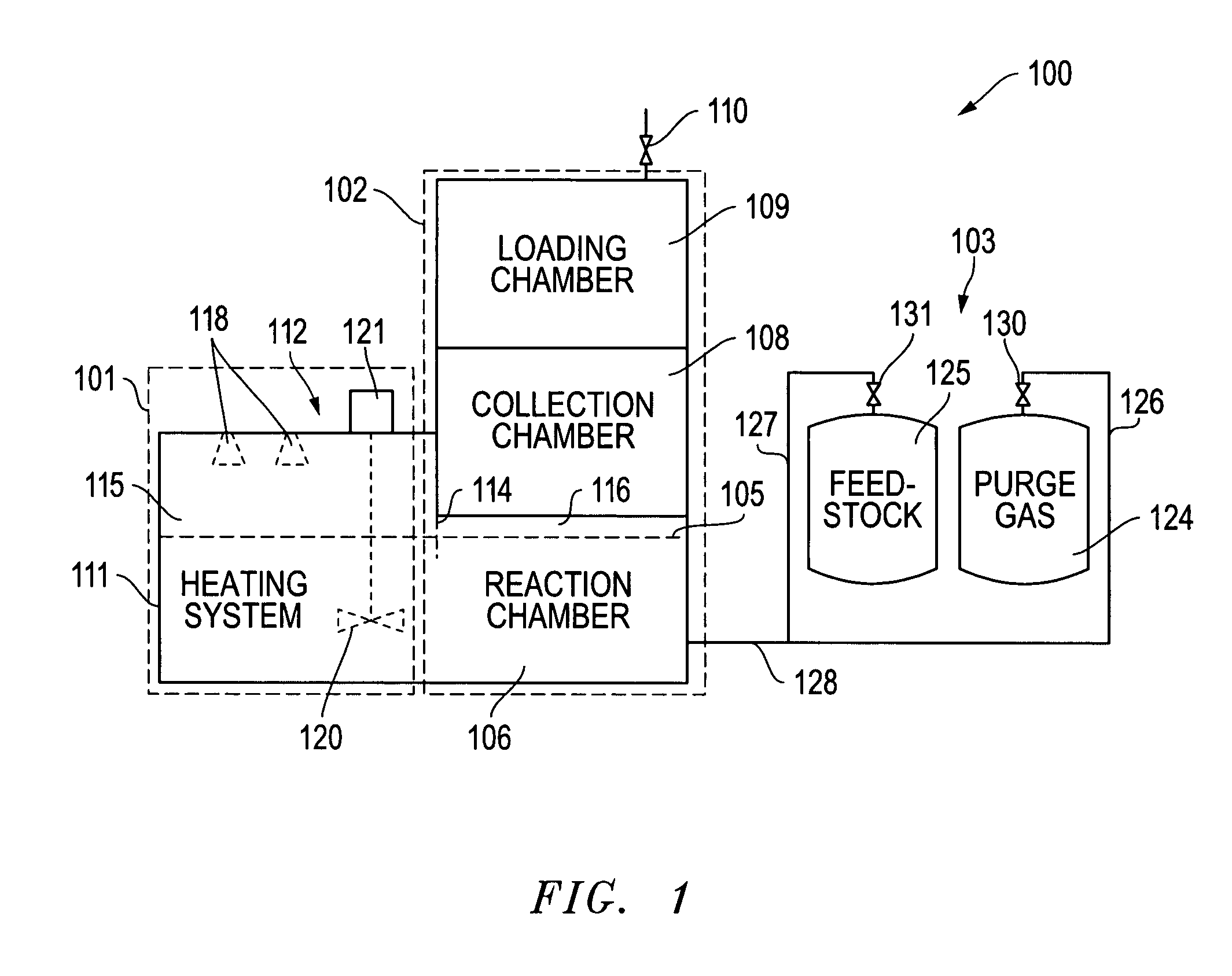
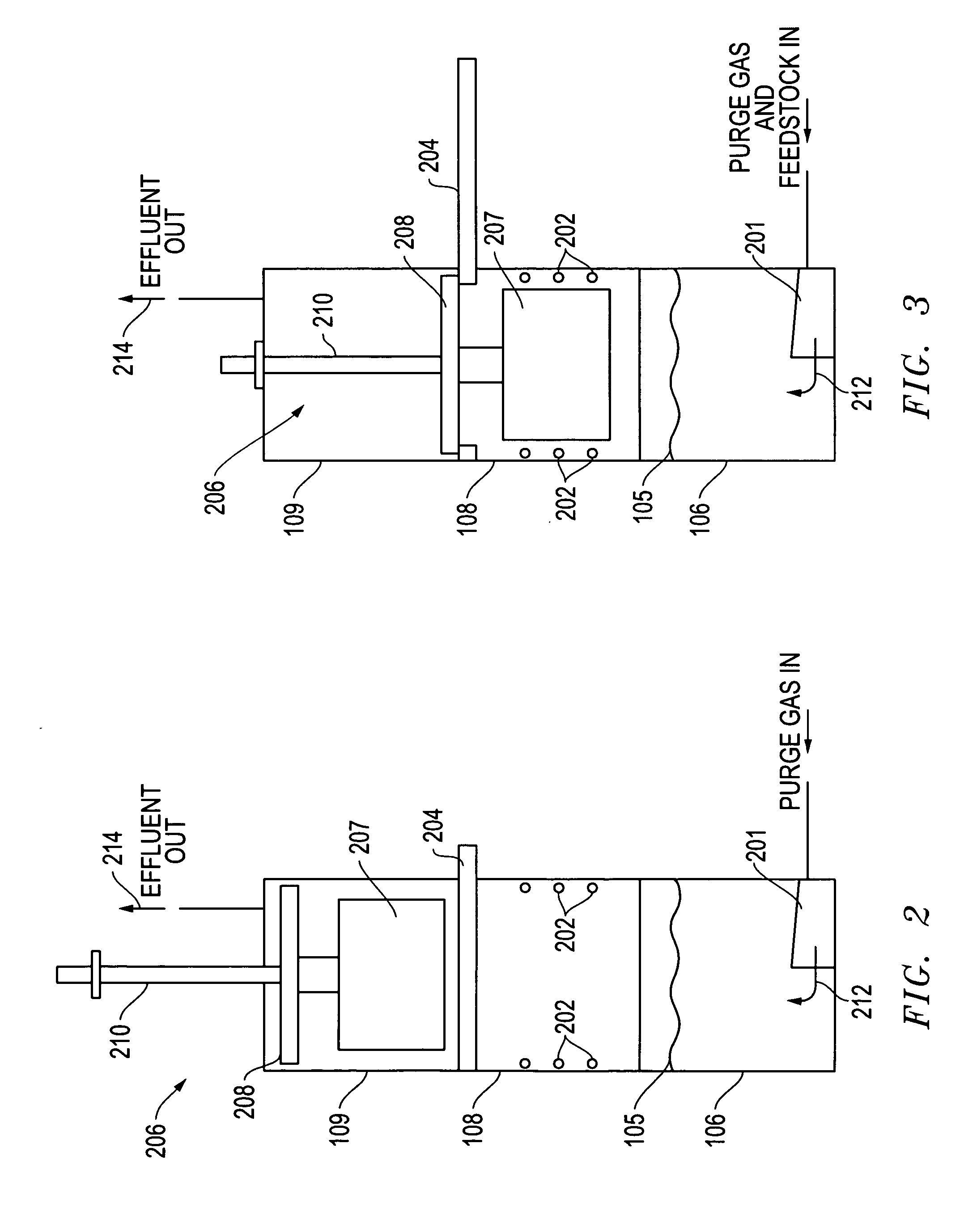
[0052] In one test of the apparatus described above, rack 501 was loaded with six horizontal collection plates 502 spaced approximately one-half inch apart and five vertical collection plates 503 spaced approximately one and one-half (1.5) inch apart. The collection structure 207 made up of rack 501 and loaded collection plates 502 and 503 was then placed into loading chamber 109 suspended on manipulating structure 210 as described above in connection with FIG. 6. The airlock door associated with loading chamber 109 was then closed and the continuously injected argon gas allowed to purge the loading chamber of air that entered as the airlock door was open. After purging loading chamber 109 of air, insulating door 204 was opened and manipulating structure 210 was used to lower collection structure 207 from the position shown in FIG. 2 to the position shown in FIG. 3. In this lowered position, with collection structure 207 residing in collection chamber 108, the lowermost ends of the ...

example 2

[0058] The same procedure described in Example 1 above was conducted in an additional series of tests each using a lower initial temperature of collection structure 207 prior to starting the injection of the acetylene-acetone mixture, and using only horizontal collection plates 502. In these collection procedures, once collection structure 207 was in the position shown in FIG. 3, heater elements 202 were not activated and the acetylene-acetone mixture was injected immediately, prior to any significant heating of the collection structure. In these tests, the starting temperature of collection structure 207 was approximately 100° F., and the ending temperature was approximately 590° F. Also, for these tests, the flow of acetylene-acetone mixture was increased to seven (7) liters per minute for the injection period of two (2) hours. FIGS. 11-13 show SEM images of material collected from one of these tests. As shown in the SEM images, these tests also produced generally spherical carbon...


PUM


Abstract

A method for producing carbon nanostructures according to the invention includes injecting acetylene gas into a reactant liquid. The injected acetylene molecules are then maintained in contact with the reactant liquid for a period of time sufficient to break the carbon-hydrogen bonds in at least some of the acetylene molecules, and place the liberated carbon ions in an excited state. This preferred method further includes enabling the liberated carbon ions in the excited state to traverse a surface of the reactant liquid and enter a collection area. Collection surfaces are provided in the collection area to collect carbon nanostructures.

Description

CROSS-REFERENCE TO RELATED APPLICATIONS [0001] This application is a continuation-in-part of U.S. patent application Ser. No. 10 / 887,695, entitled “Method and Apparatus for Producing Carbon Nanostructures,” and U.S. patent application Ser. No. 11 / 173,419, entitled “Reactant Liquid System for Facilitating the Production of Carbon Nanostructures.” The Applicant claims the benefit of each of these applications under 35 U.S.C. §120. The entire content of each of these applications is incorporated herein by this reference.TECHNICAL FIELD OF THE INVENTION [0002] The present invention relates to methods for manufacturing carbon nanostructures having a highly ordered spherical form. In particular, the invention relates to methods for placing carbon atoms in condition to form impurity-free, spherical carbon nanostructures. The invention also includes a particular spherical carbon nanostructure. BACKGROUND OF THE INVENTION [0003] Carbon nanostructures have received a great deal of interest si...

Claims


Application Information

Patent Timeline
IPC IPC(8): D01F9/12
CPCB82Y30/00B82Y40/00C01B31/0293Y10S977/842Y10S977/844C01B32/18
Inventor WAGNER, ANTHONY S.
Owner CLEAN TECH INT
Why Eureka
Try Eureka