Method for preparing decorative elements

a technology of decorative elements and methods, applied in the field of decoration, can solve the problems of high cost of laser technology, low cost of ornamental slabs, and inability to include three-dimensional ornamental elements,

Inactive Publication Date: 2007-05-24
MARON PNINA
View PDF39 Cites 13 Cited by
  • Summary
  • Abstract
  • Description
  • Claims
  • Application Information

AI Technical Summary

Benefits of technology

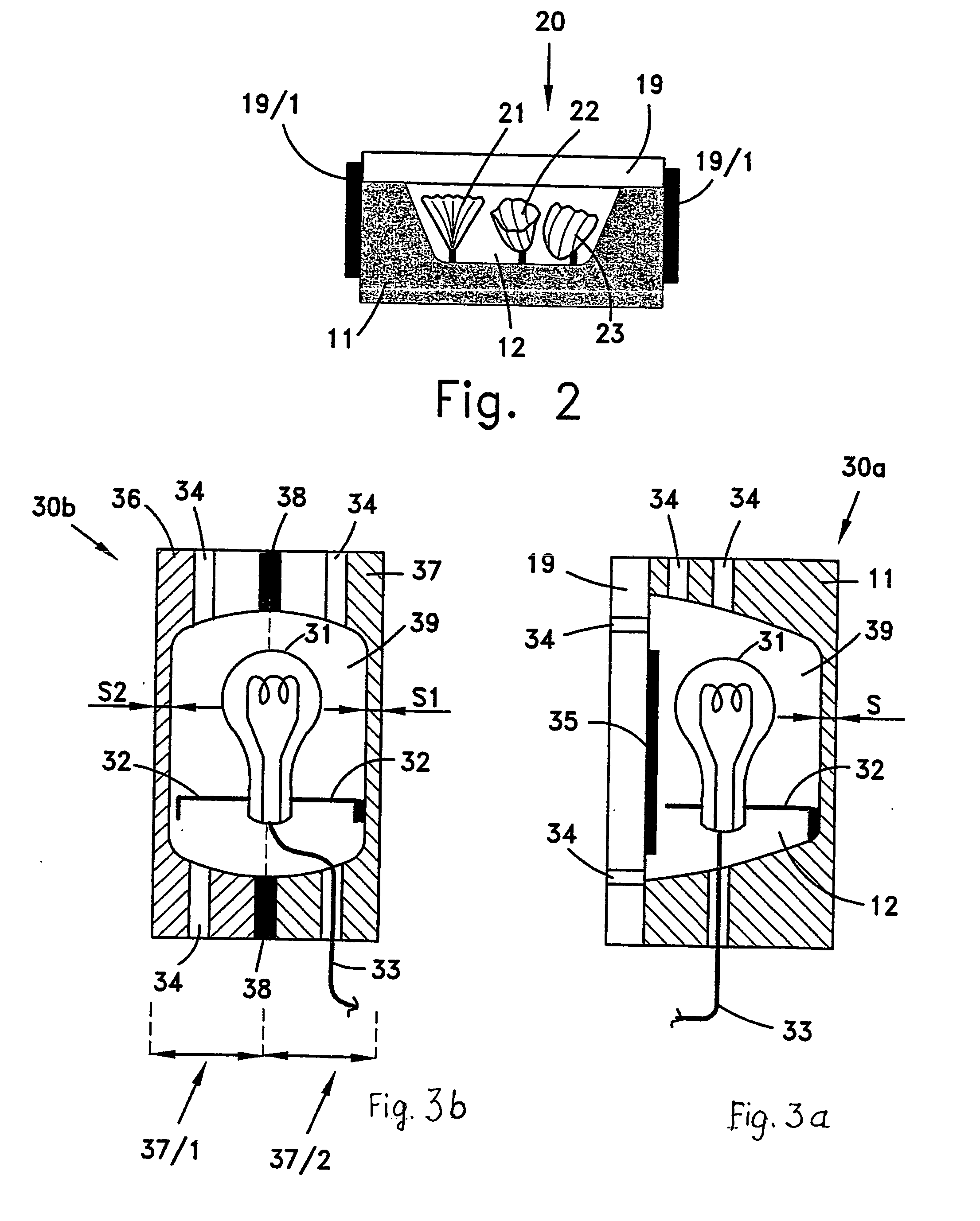
[0060] According to yet another embodiment, one or more channels (hereinafter‘light channels’) are made in the cavity or cavities, by drilling holes that pass through the slab, to allow light, which is emitted from a light source outside the ornamental slab, to penetrate, via the light channels, into the cavity or cavities for lightning the cavities and / or the ornamental / decorative elements residing therein, to obtain visual effects that are interested and appealing to a viewer.

Problems solved by technology

However, ceramic tiles are usually thin and therefore can not include three dimensional ornamental elements.
In addition, laser technology is expensive, which would render the ornamental slabs, produced by its utilization, expensive.
In addition, none of the prior art publications teaches either how to rapidly sandblast deep cavities in a stone or the like., in particular in White Granite (known by its commercial names as Porcelain Granite, White Ironstone, Pearl China, Pearl Granite, Flintware, and Opaque China) or in other materials having similar hardness, or how to incorporate three dimensional decorative elements into a deep cavity created in a stone, wood or the like, which could then be utilized, for example, to cover a floor or a wall of an apartment, or be used as a ‘stand-alone’ decorative element.

Method used


Image

  • Method for preparing decorative elements
  • Method for preparing decorative elements
  • Method for preparing decorative elements

Examples


Embodiment Construction

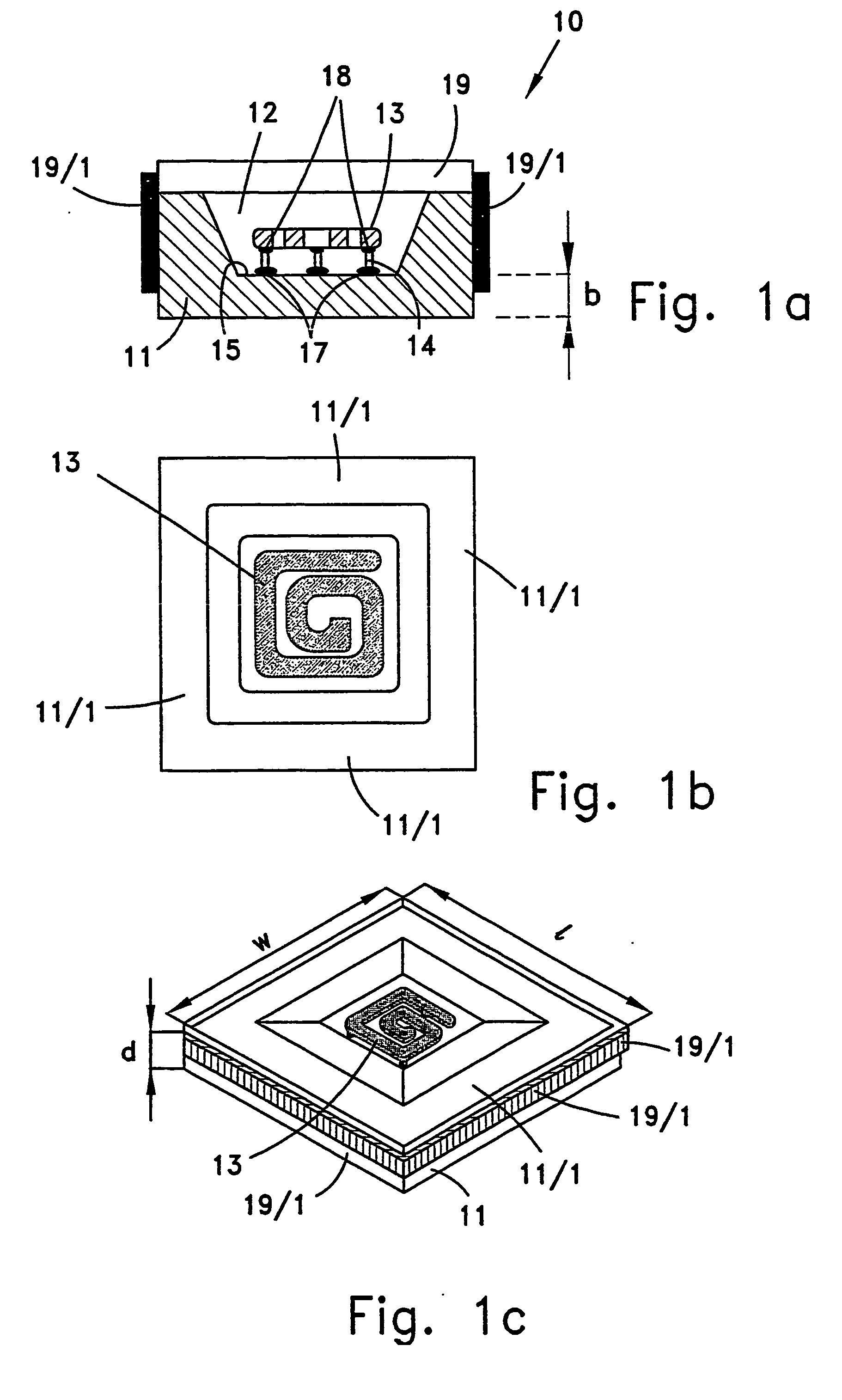
[0080]FIG. 1 is a sectional view of an exemplary ornamental slab, according to the principles disclosed in the present invention. Ornamental slab 10 comprises, e.g., stone 11, in which cavity 12 is cut, preferably by sandblasting stone 11. Ornamental element 13 (best shown in FIG. 1b) is secured in cavity 12 by utilizing supporting elements 14. The proximal end of supporting elements 14 (in this example, a total of three supporting elements) is adhered (17) to bed 15 of cavity 12, by utilizing corresponding adhering agent (e.g., Epoxy resin). Then, ornamental element 13 is put in its place in cavity 12 and adhered (18) to the distal end of supporting elements 14. Covering sheet (e.g., made of glass) 19 is then put against the open side of cavity 12, for providing sealing (i.e., against water and moisture) and mechanical protection to ornamental element 13. Covering glass 19, which could be fully transparent in whole or in part, fully colored, or a combination of transparent and colo...


PUM

PropertyMeasurementUnit
thicknessaaaaaaaaaa
sizeaaaaaaaaaa
thicknessaaaaaaaaaa

Abstract

A process for making a slab of, e.g., stone, wood, White Granite and the like, decorative element, by sandblasting therein a relatively deep cavity, using a jet of particles having at least hardness 7 that are forced through a resilient PVC (Poly Vinyl Chloride) mask, which protects the surfaces of the slab that are not intended to be sandblasted. Using the PVC mask allows obtaining a rather deep cavity in the slab without having to frequently replace the mask due to wear, and also allows obtaining cavities with edges that have contour lines that are essentially identical to the contour lines of the windows in the mask. Utilization of PVC masks impart to the cavities conspicuous artistic appearance, thereby beatifying the appearance of the ornamental slab. Then, the slab is made an ornamental slab, by incorporating two and/or three dimensional ornamental elements (e.g., dried flowers, shells of various kinds, clams, cockles, scallops, blue mussels, various colored stones, metal plastic or wood elements, mirrors, pearls, light sources, etc.) into the cavity. Then, the cavities are covered with a covering sheet for protecting the ornamental elements residing therein. The covering sheet is made of a desired material, which may be transparent or semi-transparent, and may have different shapes and colors.

Description

FIELD OF THE INVENTION [0001] The present invention relates to the field of decoration. More particularly, the present invention relates to a process for making a slab of, e.g., stone, wood, and the like, decorative element. BACKGROUND OF THE INVENTION [0002] Ever since the dawn of civilization, stones have been a major component in various aspects of the culture of human beings. For example, stones have long been utilized as memorial markers, for memorializing the deceased. In some cultures, stones, having random shape and sizes, were just put over burial sites, to mark the burial location. In other cultures, the memorial stones were embellished in various ways, for example, by carving, or etching, the stones. Carved stones and wood have also been utilized for adorning the exterior and interior sides of buildings, and as ‘stand-alone’ pieces of art. [0003] Stone slabs have also been utilized as tiles, for paving roadways, covering floors of apartments and for covering walls. In som...

Claims


Application Information

Patent Timeline
Patent Type & Authority Applications(United States)
IPC IPC(8): B24B1/00B05B15/04B05C21/00B24C1/04B41N1/24B44C1/22B44C3/04B44C3/10
CPCB44C1/22B44C1/221B44C3/046B44C3/10E04F13/08E04F15/02E04F2290/026F21S8/022F21V33/006F21Y2101/02F21Y2115/10
Inventor MARON, PNINA
Owner MARON PNINA
Why Eureka
Try Eureka