Sensor diagnostics using embedded model quality parameters

a sensor and model technology, applied in the direction of machines/engines, instruments, analogue processes for specific applications, etc., can solve the problems of changing the physical size and shape of the engine system, difficult diagnosis of in-range sensor values, and affecting engine performance and efficiency

Active Publication Date: 2007-05-24
GENERAL ELECTRIC CO
View PDF24 Cites 60 Cited by
  • Summary
  • Abstract
  • Description
  • Claims
  • Application Information

AI Technical Summary

Benefits of technology

[0016] An advantage of the present invention is the ability to detect in-range sensor failures that would not otherwise be detected by conventional control systems which only detect sensor failures when the sensor values drift out of their normal range.
[0017] Another advantage of the present invention is that an engine model embedded within a control or diagnostic system may be prevented from fo

Problems solved by technology

Out -of-range sensor failures are readily detected by FADEC logic but in-range sensor values are difficult to diagnose.
Examples of such changes are wear and distortion, which change the physical size and shape of the engine system, sub-system, or component.
Such changes in physical properties often reduce or impair engine performance and efficiency, leading to increased fuel consumption, and reduced engine life.
As an engine deteriorates and undergoes physical changes over time, the physical properties of the deteriorated engine system, sub-system, or components start to deviate from the physical properties that were originally pre-programmed into the engine control system.
If direct feedback of the changing physical properties from the engine to the control system is not available (as is the case in contemporary engine control systems), then the control system cannot account for the physical changes.
The resulting deviations between the deteriorated physical properties (in the engi

Method used


Image

  • Sensor diagnostics using embedded model quality parameters
  • Sensor diagnostics using embedded model quality parameters
  • Sensor diagnostics using embedded model quality parameters

Examples


Embodiment Construction

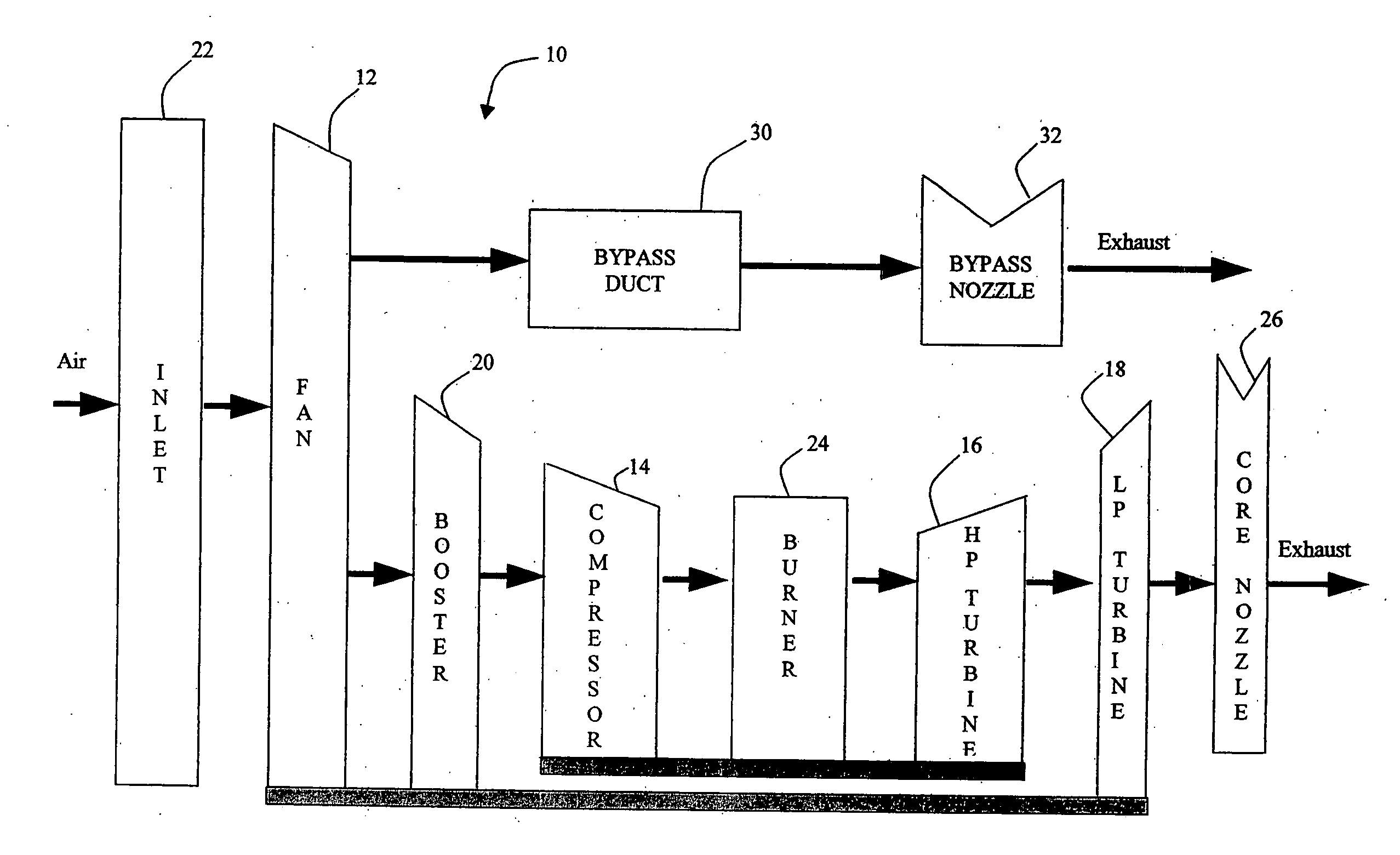
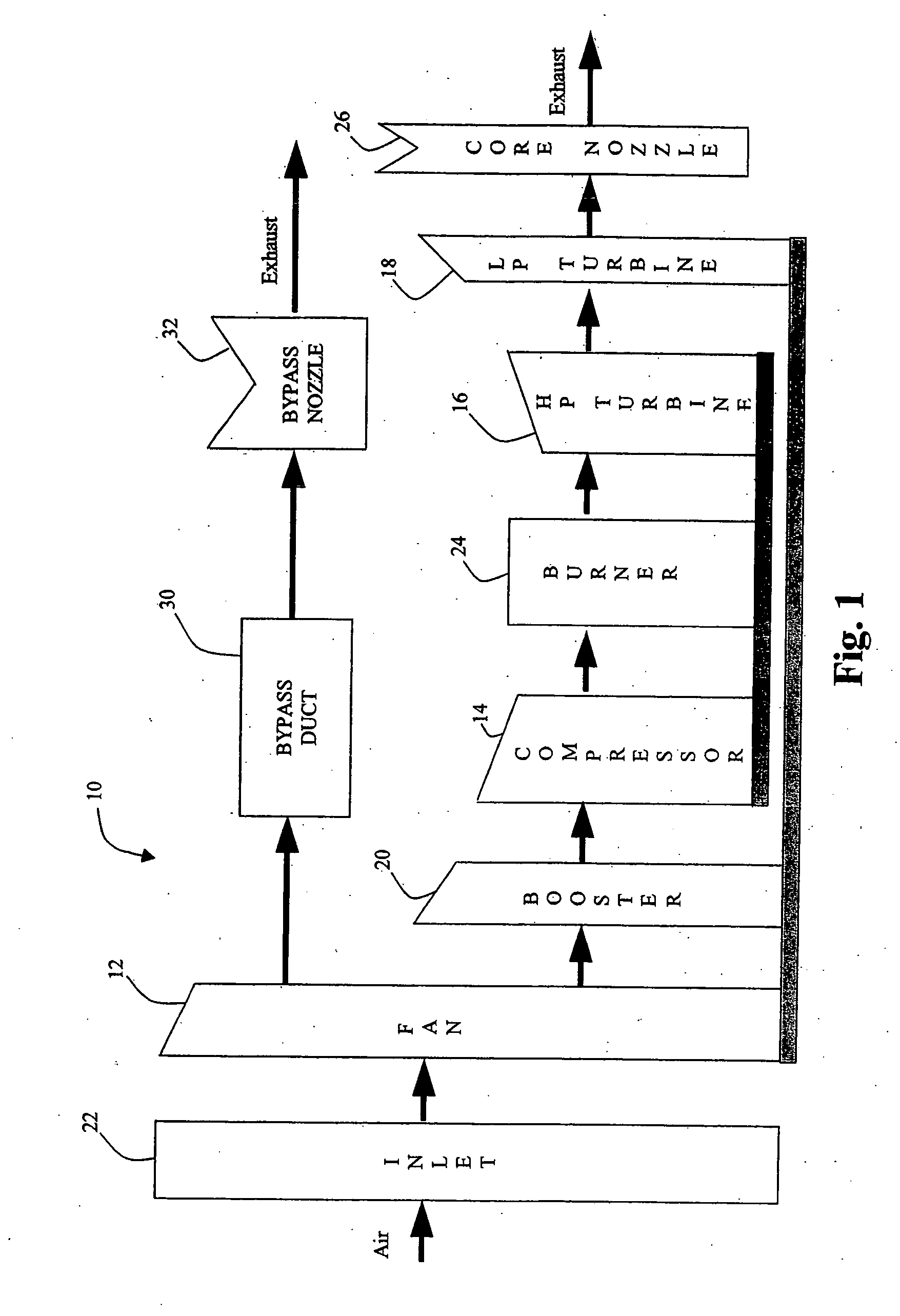
[0023] Referring to FIG. 1, the Component Level Model (CLM) 10, as illustrated, represents a physics based model. An embedded model of the engine 10 is employed to estimate sensed parameters such as rotor speeds, temperatures and pressures, as well as parameters such as stall margin, thrust and airflow, based on input parameters. Input parameters include environmental conditions, power setting and actuator position. The embedded model may be a physics-based model, a regression fit or a neural network model. The preferred embodiment uses a physics-based aerothermodynamic engine model to individually model each major rotating component of the engine, including the fan 12, compressor 14, combustor 24, turbines 16, 18, duct, 30 and nozzles, 26, 32.

[0024] The CLM 10 is designed to be a fast running, transient engine cycle representation, with realistic sensitivities to flight conditions, control variable inputs and high-pressure compressor bleed. The quality parameters for the CLM compr...


PUM


Abstract

A method and system is provided for identifying in-range sensor faults in a gas turbine engine, by observing the tracked component qualities in an embedded model and recognizing anomalous patterns of quality changes corresponding to sensor errors. An embedded model of the engine is employed to estimate sensed parameters such as rotor speeds, temperatures and pressures, as well as other parameters that are computed based on input parameters. Each major rotating component of the engine, including the fan, compressor, combustor, turbines, ducts and nozzle is individually modeled. Sensor failures are detected by identifying anomalous patterns in component quality parameters. A library of anomalous patterns is provided for comparing quality parameters generated by a tracking filter with the library of anomalous patterns. If a pattern is matched, a sensor may be eliminated from the tracking filter and the estimated model parameter used to avoid corrupting the model quality parameters.

Description

FIELD OF THE INVENTION [0001] The present invention is directed to a method and system for controlling a gas turbine engine, and more particularly to a method and system for detecting in-range sensor failures using a parameterized component level model (CLM) representing the major rotating components of the engine. BACKGROUND OF THE INVENTION [0002] Existing gas turbine engines typically utilize a digital / electronic engine control system, often referred to as FADEC (Full Authority Digital Electronic Control). FADEC includes mathematical and computational models of various engine systems, sub-systems, and components. These mathematical / computational models are often used to predict and control the behavior of engine systems, sub-systems, and components. Prediction and control of engine behavior may utilize (1) feedback of actual engine behavior by means of sensors located in various parts of the engine (temperature, pressure, speed, etc.), (2) calculations and predictions of engine s...

Claims


Application Information

Patent Timeline
IPC IPC(8): G06F19/00
CPCF01D17/24F02C9/00F05D2270/54F05D2260/81F05D2260/80
Inventor WISEMAN, MATTHEW WILLIAMASHBY, MALCOLM JOHN
Owner GENERAL ELECTRIC CO
Why Eureka
Try Eureka