Transflective display having full color oled blacklight

a technology of oled blacklight and reflector, which is applied in the field of illumination devices, can solve the problems of reducing efficiency, affecting the effect of illumination, and affecting the efficiency of small lamps, so as to enhance the reflection ratio of the reflective electrode, enhance the outcoupling effect, and increase the aperture ratio

Active Publication Date: 2007-05-31
UNIVERSAL DISPLAY
View PDF4 Cites 29 Cited by
  • Summary
  • Abstract
  • Description
  • Claims
  • Application Information

AI Technical Summary

Benefits of technology

[0008] The present invention combines a conventional organic light emitting diode (OLED) having one reflective electrode and at least one transparent OLED in stacked configuration functioning as backlighting in a transflective display apparatus such as a liquid crystal display (LCD). Preferably, at least two transparent OLEDs are arranged in a stacked configuration with one conventional OLED, each of the three OLEDs emitting light of a different bandwidth. This arrangement permits color sequencing in the transmissive mode, allowing all the components of a full color display (i.e. red, green, blue) to emit through the same pixel without the need for a color filter. Since each pixel does not need to be subdivided into red, green and blue sub-pixels, the aperture ratio is increased by approximately a factor of three. The three OLED stack thus comprises a full color backlight in which the transparent OLEDs are positioned be...

Problems solved by technology

Generally, the result is to produce a relatively large and cumbersome package, usually with several discrete components that may be difficult to incorporate in portable electronic equipment, or the like.
Fluorescent lamps are suitable for lighting large direct view LCDs, but are a problem at the smaller sizes including virtual image displays.
As a general rule, as the length and diameter of the lamps decrease, the efficiency also decreases, making small lamps very power hungry.
In addition, the individual red, green and blue emission from the fluorescent lamps cannot be controlled individually, thus field sequential ...

Method used


Image

  • Transflective display having full color oled blacklight
  • Transflective display having full color oled blacklight
  • Transflective display having full color oled blacklight

Examples


Embodiment Construction

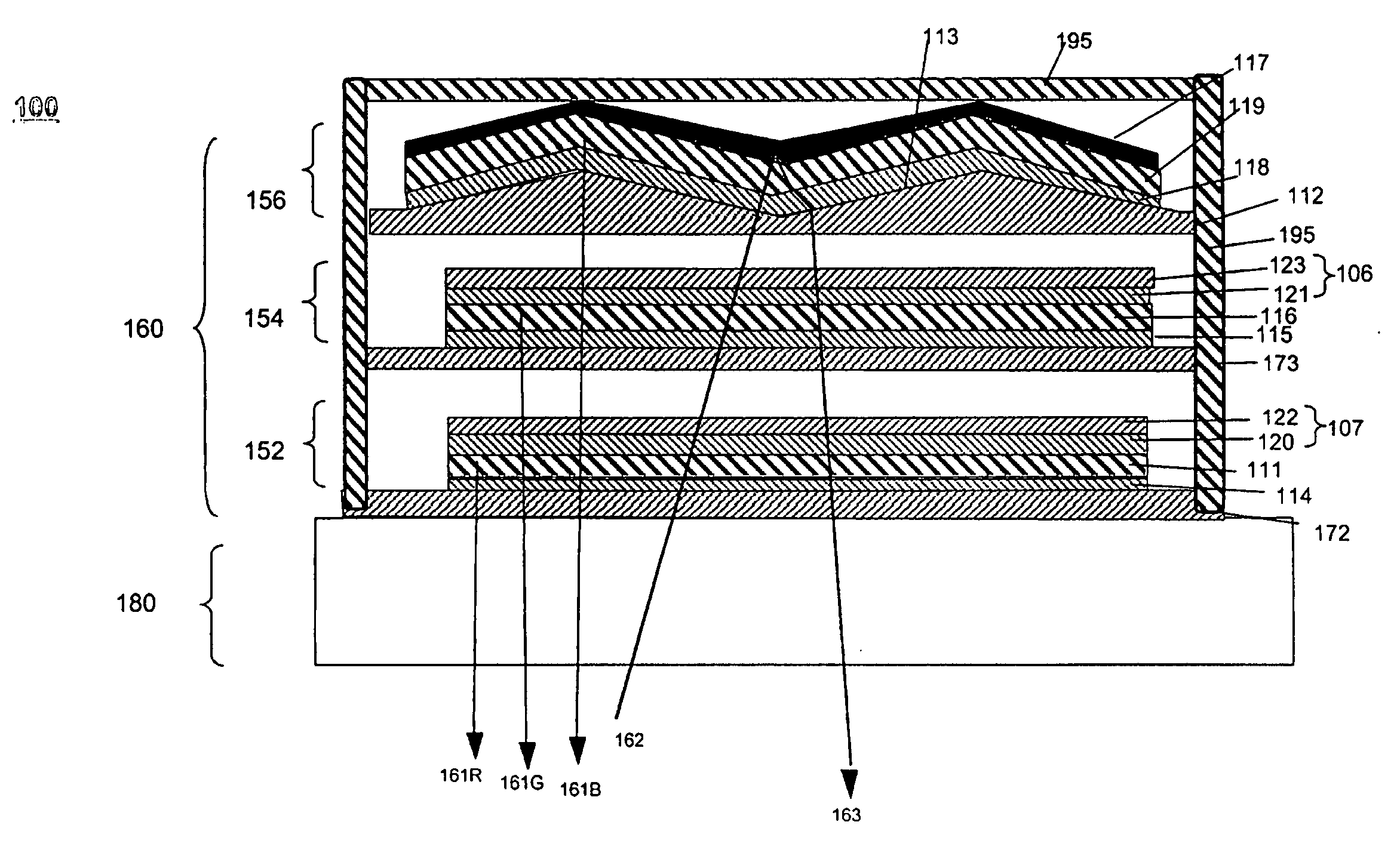
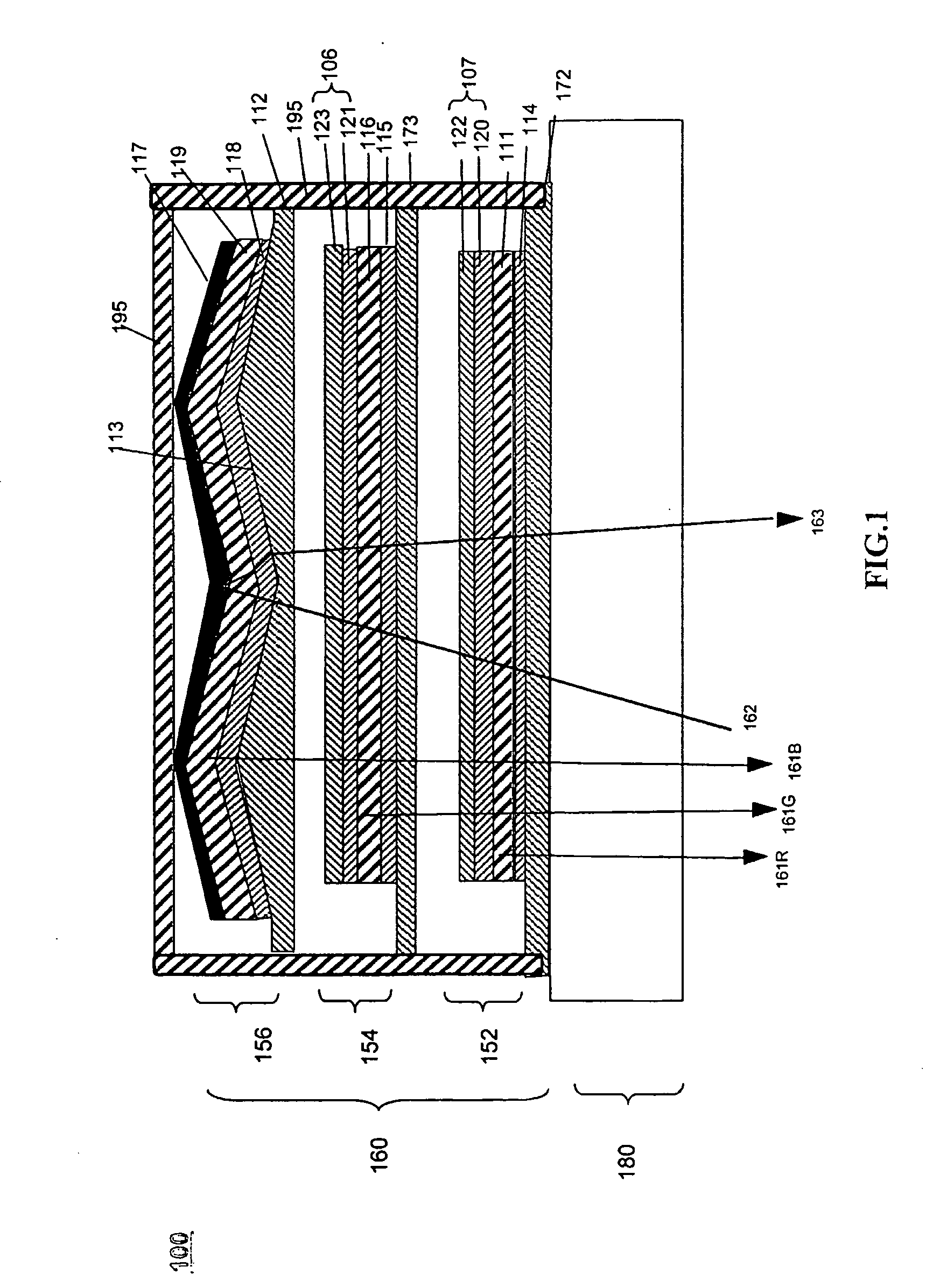
[0013] OLEDs make use of thin organic films that emit light when voltage is applied across the device. OLEDs are becoming an increasingly interesting technology for use in applications such as flat device displays, illumination, and backlighting. Several OLED materials and configurations are described in U.S. Pat. Nos. 5,844,363, 6,303,238, and 5,707,745, which are incorporated herein by reference in their entireties.

[0014] As used herein a “conventional OLED” device is one that is intended to emit light through only one of the electrodes. Thus only one of the electrodes is transparent while the other is reflective and, preferably, opaque. For a device intended to emit light only through the bottom electrode, the top electrode (i.e., the cathode) is reflective rather than transmissive and may be comprised of an opaque metal layer having a high electrical conductivity. A transparent conductive material, such as indium tin oxide (ITO), may be used as the bottom electrode. Similarly, ...


PUM


Abstract

Disclosed is a conventional organic light emitting diode (OLED) having one reflective electrode in combination with at least one transparent OLED in stacked configuration functioning as backlighting in a transflective display apparatus such as a liquid crystal display (LCD). Preferably, at least two transparent OLEDs are arranged in a stacked configuration with one conventional OLED, each of the three OLEDs emitting light of a different bandwidth. The reflective electrode located behind the backlight also serves as a reflecting plate for the display. This arrangement enhances reflectivity and permits color sequencing in the transmissive mode, allowing all the components of a full color display (i.e. red, green, blue) to emit through the same pixel without the need for a color filter.

Description

FIELD OF THE INVENTION [0001] The present invention pertains to illumination devices and more specifically to packaging and illumination of OLED backlights for use in liquid crystal displays. BACKGROUND OF THE INVENTION [0002] Liquid crystal displays (LCDs) are utilized in a great variety of direct view type displays and virtual image displays. Examples of direct view displays in which LCDs are utilized include digital watches, telephones, lap-top computers and the like. Examples of virtual image displays in which LCDs are utilized include camcorder viewfinders, head-mounted displays, or virtual displays in portable electronic equipment, such as portable communications equipment. [0003] Liquid crystal displays have three basic modes: transmissive, reflective and transflective. In transmissive mode, the LCD pixels are illuminated from behind (i.e. opposite the viewer) typically using a cold cathode fluorescent lamp (CCFL) or LED. Transmissive LCDs offer the best performance under lig...

Claims


Application Information

Patent Timeline
IPC IPC(8): H01J1/62H01J63/04G02F1/1335G02F1/13357G09G3/34H01L27/32H01L51/50H01L51/52
CPCG02F1/133555G02F1/133603G02F2001/133622G02F2001/133626G09G3/3426G09G2310/0235H01L27/3209H01L51/52H01L51/5237H01L51/5268H01L51/5271H01L2251/5323H01L25/048H01L2924/0002G02F1/133622G02F1/133626H10K59/90H10K59/32H10K50/80H10K50/8445H10K50/841H10K50/854H10K50/856H10K2102/3031H01L2924/00H05B33/26H05B33/28H05B33/14G02F1/1335
Inventor ITO, HIRONORIKOIDE, NAOTAKATUNG, YEH-JIUNHACK, MICHAELBROWN, JULIA
Owner UNIVERSAL DISPLAY
Why Eureka
Try Eureka