Driving method for liquid crystal display device assembly

a liquid crystal display and assembly technology, applied in the direction of instruments, static indicating devices, etc., can solve the problems of increasing the luminance level of the full-black display portion, making the display state on the screen unnatural compared with other types of display devices, and no specific method of increasing the luminance level of the white display portion to a level higher than the luminance level of the other display portions, so as to achieve the effect of enhancing the contrast ratio and increasing the luminan

Active Publication Date: 2007-05-31
SATURN LICENSING LLC
View PDF7 Cites 17 Cited by
  • Summary
  • Abstract
  • Description
  • Claims
  • Application Information

AI Technical Summary

Benefits of technology

[0069] In the first driving method according to an embodiment of the present invention, for controlling the light transmittance of each pixel forming each display area unit, when the input signal value x input into the drive circuit is greater than or equal to the upper limit threshold k1·xmax, which is obtained by multiplying the input signal maximum value xmax with k1 (k1<1), the luminance of a planar light source unit corresponding to the display area unit that achieves increased luminance is controlled (increased) by the drive circuit so that the luminance of a pixel, assuming that a control signal corresponding to an input signal having a value obtained by adding a bias k0·xmax to the input signal value xU-max is supplied to the pixel, can be obtained. Accordingly, the luminance of the display area unit including a display portion (also referred to as a “white display portion” including pixels to which a control signal corresponding to an input signal greater than or equal to the upper limit threshold is supplied) can be increased to a level higher than the luminance

Problems solved by technology

In this approach, however, the luminance of the full-black display portion is also increased, and the so-called “graying of a black color” phenomenon occurs, which makes the display state on the screen unnatural compared with other types of display devices.
In

Method used


Image

  • Driving method for liquid crystal display device assembly
  • Driving method for liquid crystal display device assembly
  • Driving method for liquid crystal display device assembly

Examples


first embodiment

[0117] In a first embodiment, a driving method for a liquid crystal display device assembly is described. Specific values of various parameters used in the first through ninth embodiments are defined as follows.

xmax=256

k0=0.125

k1=0.9375

k1·xmax=240

k0·xmax=32

k2=0.485

α0=1.00

α1=0.7

α2=0.1

[0118] Dmax=duty ratio that can obtain 714 cd / M2 in a display area unit in a color liquid crystal display device

[0119] D0=Dmax

[0120] D1=duty ratio that can obtain 500 cd / M2 in a display area unit in a color liquid crystal display device

[0121] D2=duty ratio that can obtain 71 cd / M2 in a display area unit in a color liquid crystal display device

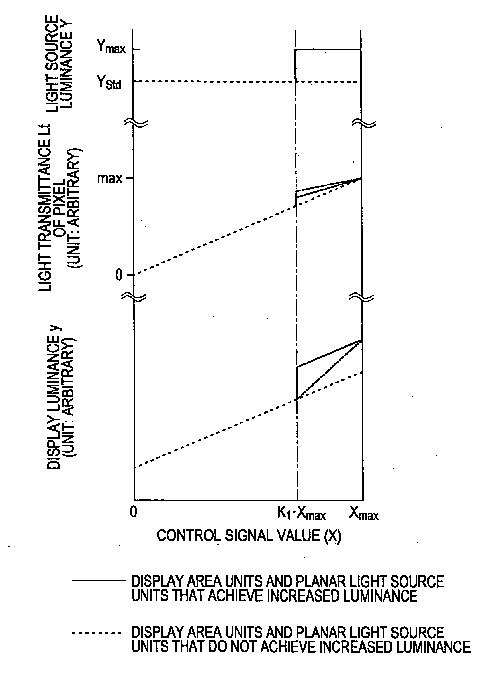
[0122] The relationships of the value X of a control signal supplied to a pixel to the light source luminance Y and the light transmittance (aperture ratio) Lt and the display luminance y of sub-pixels in the first through ninth embodiments are schematically shown in FIGS. 1 through 9. In FIGS. 1 through 9, the solid lines indicate the behaviors of the...

second embodiment

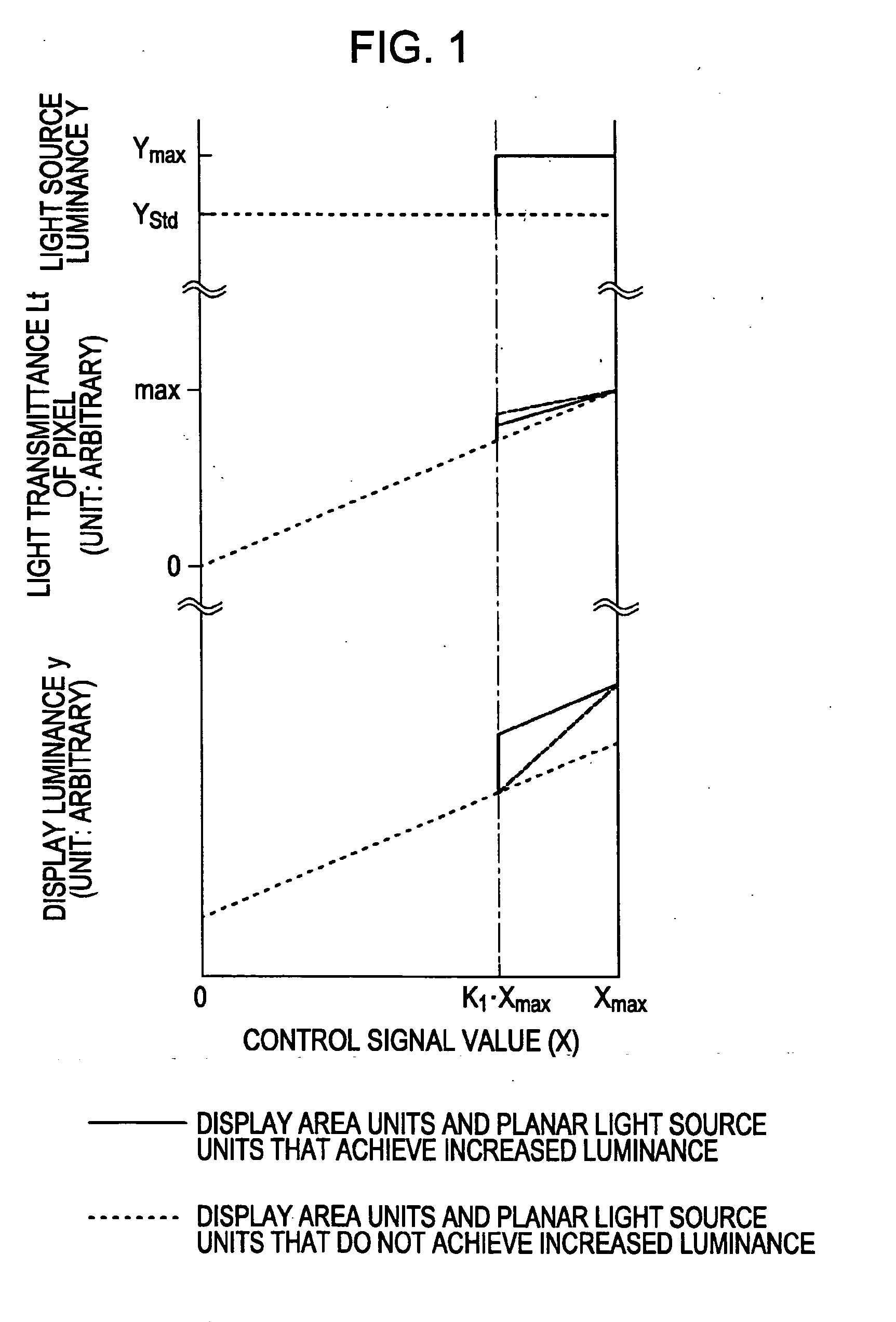
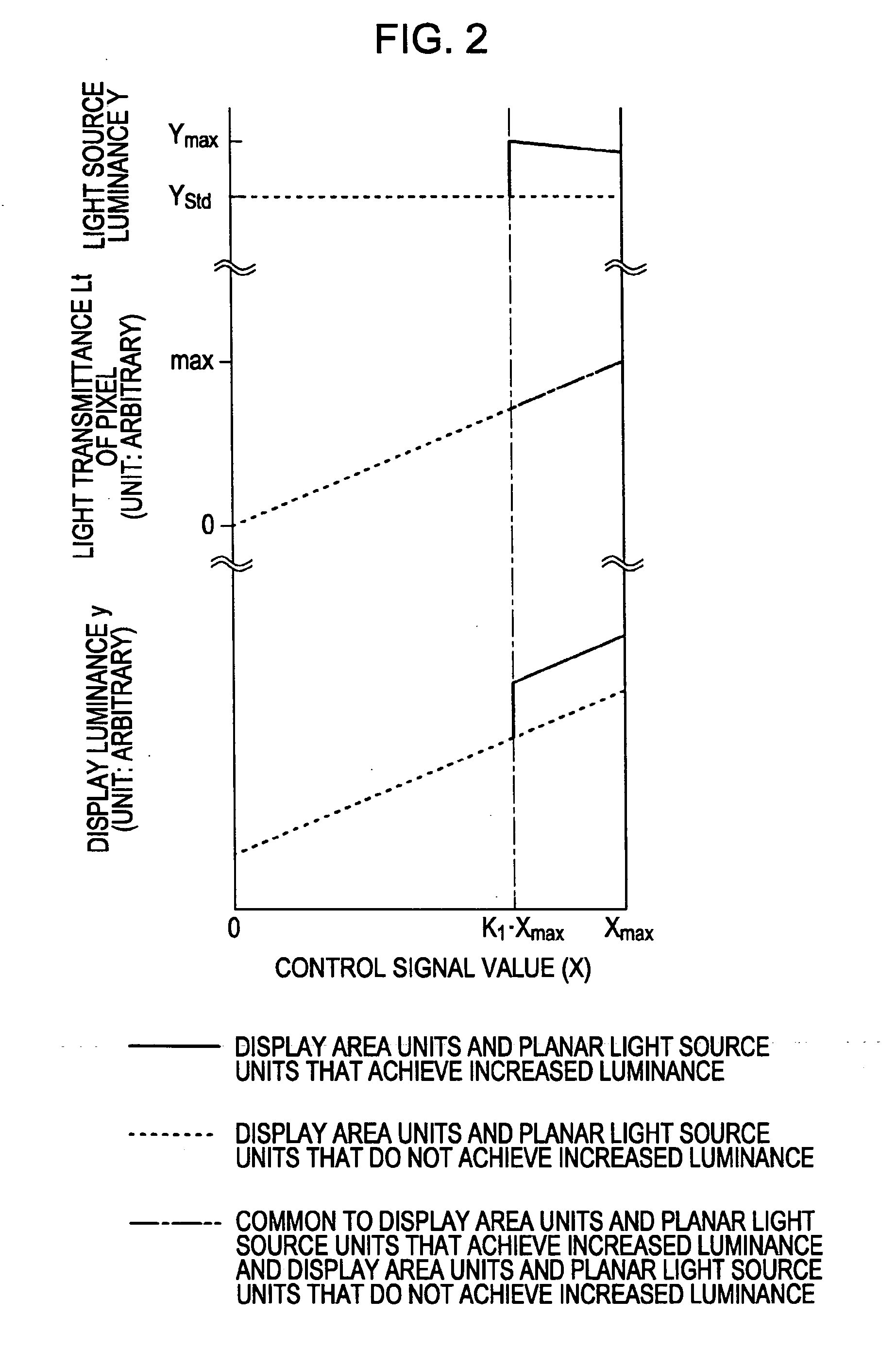
[0140] In a second embodiment, which is a modification made to the first embodiment, the control mode 1B and the control mode 2A are employed. That is, in steps S220A and S220B similar to steps S120A and S120B in the first embodiment, control mode 1B is employed. The relationships of the control signal value X to the light source luminance Y and the light transmittance Lt and the display luminance y of sub-pixels in the second embodiment are schematically shown in FIG. 2. A description is now given, with reference to FIGS. 11A and 11B and 16, of a driving method for a liquid crystal display device assembly according to the second embodiment. FIGS. 11A and 11B illustrate the concept of the relationship among the light source luminance of the planar light source device 40, the light transmittance (aperture ratio), and the display luminance of pixels in the control mode 1B. FIG. 16 is a flowchart illustrating the driving method for the liquid crystal display device assembly.

[0141] In ...

third embodiment

[0147] In a third embodiment, which is also a modification made to the first embodiment, the control mode 1C and the control mode 2A are employed. That is, in steps S320A and S320B similar to steps S120A and S120B in the first embodiment, control mode 1C is employed. The relationships of the control signal value X to the light source luminance Y and the light transmittance Lt and the display luminance y of sub-pixels in the third embodiment are schematically shown in FIG. 3. A description is now given, with reference to FIGS. 12A and 12B and 17, of a driving method for a liquid crystal display device assembly according to the third embodiment. FIGS. 12A and 12B illustrate the concept of the relationship among the light source luminance of the planar light source device 40 of pixels, and the light transmittance (aperture ratio) and the display luminance y of pixels in the control mode 1C. FIG. 17 is a flowchart illustrating the driving method for the liquid crystal display device ass...


PUM


Abstract

A driving method for a liquid crystal display device assembly that includes a transmissive-type liquid crystal display device, a planar light source device including P×Q planar light source units, and a drive circuit that drives the two devices is disclosed. The driving method includes the step of, when the value of an input signal input into the drive circuit is indicated by x, in each of the display area units, when the value x of the input signal for any of the pixels is greater than or equal to a predetermined value, such a value being indicated by xU-max, controlling the luminance level of the planar light source unit corresponding to the display area unit so that luminance levels of the pixels, assuming that the control signal corresponding to the input signal having a value greater than the value xU-max is supplied to the pixels, can be obtained.

Description

CROSS REFERENCES TO RELATED APPLICATIONS [0001] The present invention contains subject matter related to Japanese Patent Application JP 2005-343320 filed in the Japanese Patent Office on Nov. 29, 2005 and Japanese Patent Application JP 2006-244330 filed in the Japanese Patent Office on Sep. 8, 2006 the entire contents of which are incorporated herein by reference. BACKGROUND OF THE INVENTION [0002] 1. Field of the Invention [0003] The present invention relates to a method for driving a liquid crystal display device assembly including a liquid crystal device and a planar light source device. [0004] 2. Description of the Related Art [0005] In liquid crystal display devices, a liquid crystal material does not emit light by itself. Instead, a direct-lighting-type planar light source device (backlight) is disposed at the back surface of a liquid crystal display device to emit light. In color liquid crystal display devices, one pixel is formed of three sub-pixels, such as a red (R) light-...

Claims


Application Information

Patent Timeline
IPC IPC(8): G09G3/18
CPCG09G3/3413G09G3/3426G09G3/3611G09G2320/064G09G2320/0646G09G2320/066G09G2360/145G09G2360/16
Inventor YANAMOTO, KAORU
Owner SATURN LICENSING LLC
Why Eureka
Try Eureka