Magneto-resistance effect element having Heusler alloy compounds adjacent to spacer layer

a technology of magneto-resistance effect and heusler alloy, which is applied in the field of magneto-resistance effect elements, can solve the problems of degrading high-frequency response and large electric resistance, and achieve the effects of preventing diffusion, large electric resistance, and large magneto-resistance ratio

Inactive Publication Date: 2007-05-31
TDK CORPARATION
View PDF8 Cites 13 Cited by
  • Summary
  • Abstract
  • Description
  • Claims
  • Application Information

AI Technical Summary

Benefits of technology

[0013] In the magneto-resistance effect element of the present invention, diffusion between the spacer layer and the Heusler alloy layer is prevented, because compounds are formed at the interface between the spacer layer and the Heusler alloy layer that is arranged thereon. As a result, variation in the composition ratio of the Heusler alloy layer is prevented, leading to a high polarizability of the Heusler alloy layer, and to a large resultant MR ratio of the magneto-resistance effect element. Further, since the compounds are arranged in a dotted pattern, an increase in electric resistance of the magneto-resistance effect element, which may be caused by the compounds, is prevented, leading to an excellent high-frequency response.
[0019] According to the magneto-resistance effect element and the thin film magnetic head of the present invention, a large MR ratio can be achieved, while limiting an increase in electric resistance, by providing compounds at the interface between the Heusler alloy layer and the spacer layer in a dotted pattern. Further, according to the method of manufacturing the magneto-resistance effect element of the present invention, such a magneto-resistance effect element can be manufactured.

Problems solved by technology

However, providing such a layer alone will lead to larger electric resistance, and to a degraded high-frequency response in a CPP-type magneto-resistance effect element.

Method used


Image

  • Magneto-resistance effect element having Heusler alloy compounds adjacent to spacer layer
  • Magneto-resistance effect element having Heusler alloy compounds adjacent to spacer layer
  • Magneto-resistance effect element having Heusler alloy compounds adjacent to spacer layer

Examples


example 1

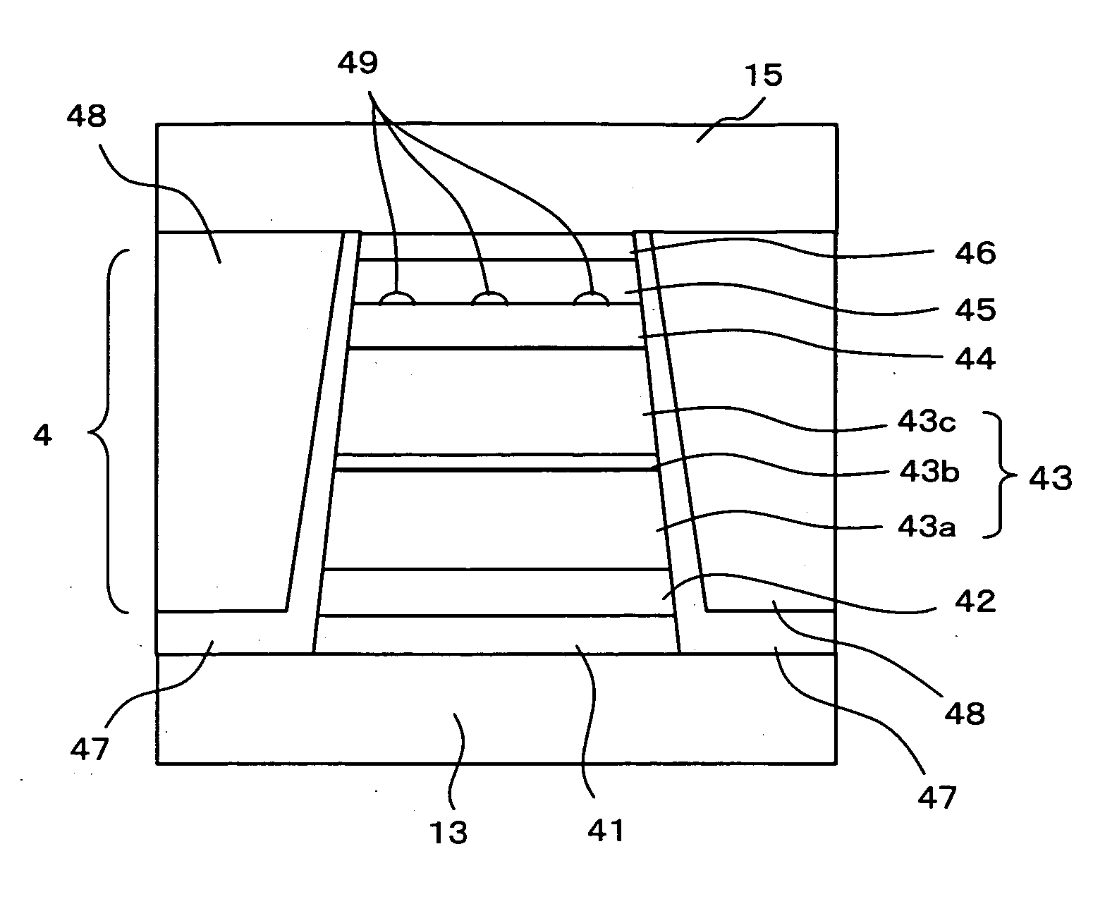
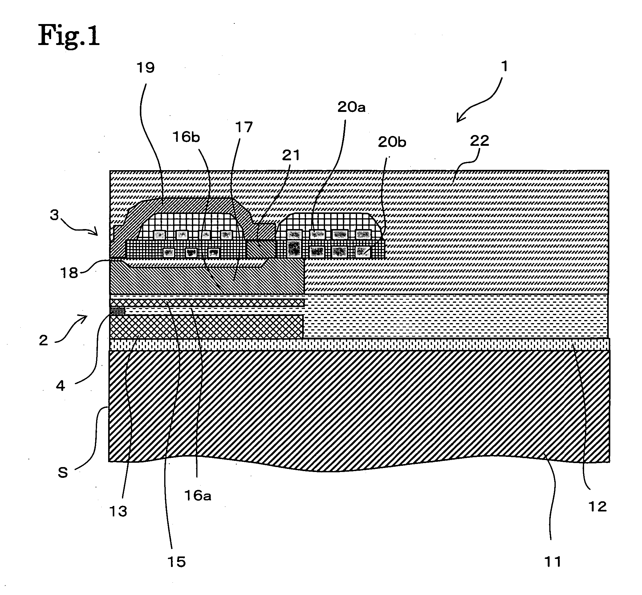
[0087] In Example 1, the MR element shown in FIG. 2 was manufactured. Table 1 shows the layer structure and the thickness of each layer.

TABLE 1MaterialThickness (nm)Cap layerRu10Free layerCoFe / NiFe1 / 2Spacer layerCu3Compounds(oxide)—Pinned layerInner layerCoFe / Heusler alloy1 / 3Intermediate layerRu0.8Outer layerCoFe / FeCo / CoFe0.5 / 0.5 / 1Antiferromagnetic layerIrMn7Buffer layerTa / NiCr1 / 5

[0088]“ / ” in Table 1 indicates that the material on the left side is arranged under the material on the right side. In other word, material on the left side is formed prior to the material on the right side.

[0089] Ten examples of the MR element were prepared which differ in the kind of material of Heusler alloy that is contained in the inner layer, the material of the compounds, and the forming method (Examples 1-1 to 1-10). A comparative example having no compounds (Comparative Example 1-1), and a comparative example having no Heusler alloy in the inner layer (Comparative Example 1-2) were also prepared...

example 2

[0093] In Example 2, the MR element shown in FIG. 4 was manufactured. Table 3 shows the layer structure and the thickness of each layer.

TABLE 3MaterialThickness (nm)Cap layerRu10Free layerHeusler alloy / CoFe2 / 2Compounds(oxide)—Spacer layerCu3Pinned layerInner layerCoFe / Heusler alloy1 / 3Intermediate layerRu0.8Outer layerCoFe / FeCo / CoFe0.5 / 0.5 / 1Antiferromagnetic layerIrMn7Buffer layerTa / NiCr1 / 5

[0094]“ / ” in Table 3 has the same meaning as in Table 1.

[0095] Eight examples of the MR element were prepared which differ in the kind of materials of Heusler alloy that is contained in the inner layer and the free layer, material of the compounds, and the forming methods (Examples 2-1 to 2-8). A comparative example having no compounds (Comparative Example 2-1), and a comparative example having no Heusler alloy in the free layer (Comparative Example 2-2) were also prepared for comparison. In the examples having compounds, the compounds were oxides. The junction size of each sample was 0.2μm×0.2μ...


PUM

PropertyMeasurementUnit
thicknessaaaaaaaaaa
pressureaaaaaaaaaa
sizeaaaaaaaaaa

Abstract

A magneto-resistance effect element according to the present invention comprises a pinned layer whose magnetization direction is fixed; a free layer whose magnetization direction varies in accordance with an external magnetic field; and a nonmagnetic spacer layer that is arranged between said pinned layer and said free layer. At least either said pinned layer or said free layer includes a Heusler alloy layer that is disposed adjacent to said spacer layer, and compounds are arranged in a dotted pattern at an interface between said spacer layer and at least said spacer layer and said pinned layer or said spacer layer and said free layer, said compounds including material that is included in said Heusler alloy layer.

Description

[0001] The present application is based on, and claims priority from, J.P. Application No. 2005-345777, filed on November, 2005, the disclosure of which is hereby incorporated by reference herein in its entirety. BACKGROUND OF THE INVENTION [0002] 1. Field of the Invention [0003] The present invention relates to a magneto-resistance effect element that is suitable for a hard disk drive. [0004] 2. Description of the Related Art [0005] A thin film magnetic head having a magneto-resistance effect element (MR element) that reads a magnetic signal is used for a hard disk drive. Since higher recording density has been realized in a hard disk drive in recent years, the need for higher sensitivity and higher output has particularly increased for the magneto-resistance effect element of a thin film magnetic head. [0006] In order to cope with such needs, a magneto-resistance effect element using a spin valve film (SV film) has been developed, which has a pinned layer whose magnetization direc...

Claims


Application Information

Patent Timeline
Patent Type & Authority Applications(United States)
IPC IPC(8): G11B5/33G11B5/127
CPCB82Y25/00B82Y40/00G01R33/093G11B5/3906H01F10/1936H01F10/3272H01F41/303H01L43/10H10N50/85
Inventor TSUCHIYA, YOSHIHIROMIZUNO, TOMOHITOSHIMAZAWA, KOJIMIYAUCHI, DAISUKE
Owner TDK CORPARATION
Why Eureka
Try Eureka