Display device provided with radiating structure and plasma display device provided with radiating structure

a technology of a display device and a radiating structure, which is applied in the direction of electrical equipment, electrical apparatus, electrical apparatus contruction details, etc., can solve the problems of increasing manufacturing costs, inability to suppress costs to an affordable level, and cramping the enclosure space of these products

Inactive Publication Date: 2007-05-31
ORION ELECTRIC CO LTD
View PDF5 Cites 19 Cited by
  • Summary
  • Abstract
  • Description
  • Claims
  • Application Information

AI Technical Summary

Benefits of technology

[0018] In the above described configuration, when a voltage is applied to the gas sealed in the display panel, the scanning electrode drive circuit substrate and the common electrode drive circuit substrate generate plasma discharge, and this causes the heat generating parts disposed on the scanning electrode drive circuit substrate and the common electrode drive circuit substrate to become hot. In this case, since the heat generating parts disposed on both of the scanning electrode drive circuit substrate and the common electrode drive circuit substrate or any one of the scanning electrode drive circuit substrate and the common electrode drive circuit substrate contact the reinforcement support members, and therefore it is possible to radiate heat of the heat generating parts generated by plasma discharge from the reinforcement support members and prevent the scanning electrode drive circuit substrate and the common electrode drive circuit substrate from becoming hot.

Problems solved by technology

A typical product of such a low-profile display device is a liquid crystal television or the like, and in response to requirements for increasingly reduced thickness, space in the enclosures of these products is becoming more and more cramped and it is considered one of problems how to cool heat generated from electronic parts in the enclosure more efficiently.
However, in the case of the above described background technology, the large-sized radiating member must be installed to cool the heat generating parts, which may cause the number of parts to increase and lead to an increase in the manufacturing cost, producing a possibility that it may be impossible to suppress cost to an affordable level and the weight of the product may be increased.
Furthermore, while Patent Document 1 describes the technology capable of cooling the heat generating electronic part by the heat sink, it neither suggests nor discloses use of a support plate or the like screwed together with a wiring substrate as a dual-function part to cool the heat generating electronic part.

Method used


Image

  • Display device provided with radiating structure and plasma display device provided with radiating structure
  • Display device provided with radiating structure and plasma display device provided with radiating structure
  • Display device provided with radiating structure and plasma display device provided with radiating structure

Examples


Embodiment Construction

[0023] Hereinafter, as the best mode for implementing the present invention, an embodiment will be explained with reference to FIG. 1 to FIG. 4. It goes without saying that the present invention is also easily applicable to modes other than that explained in the embodiment within a range not departing from the essence of the present invention.

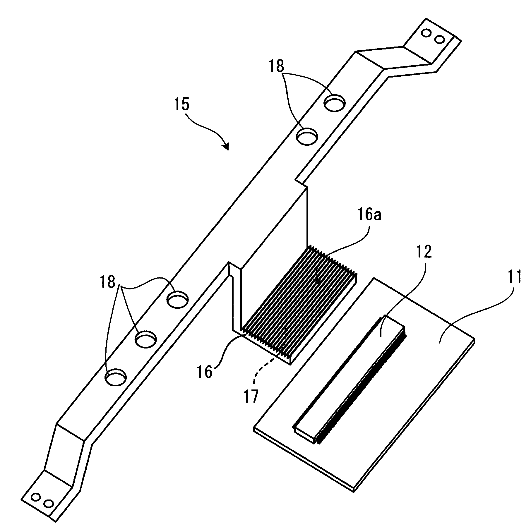
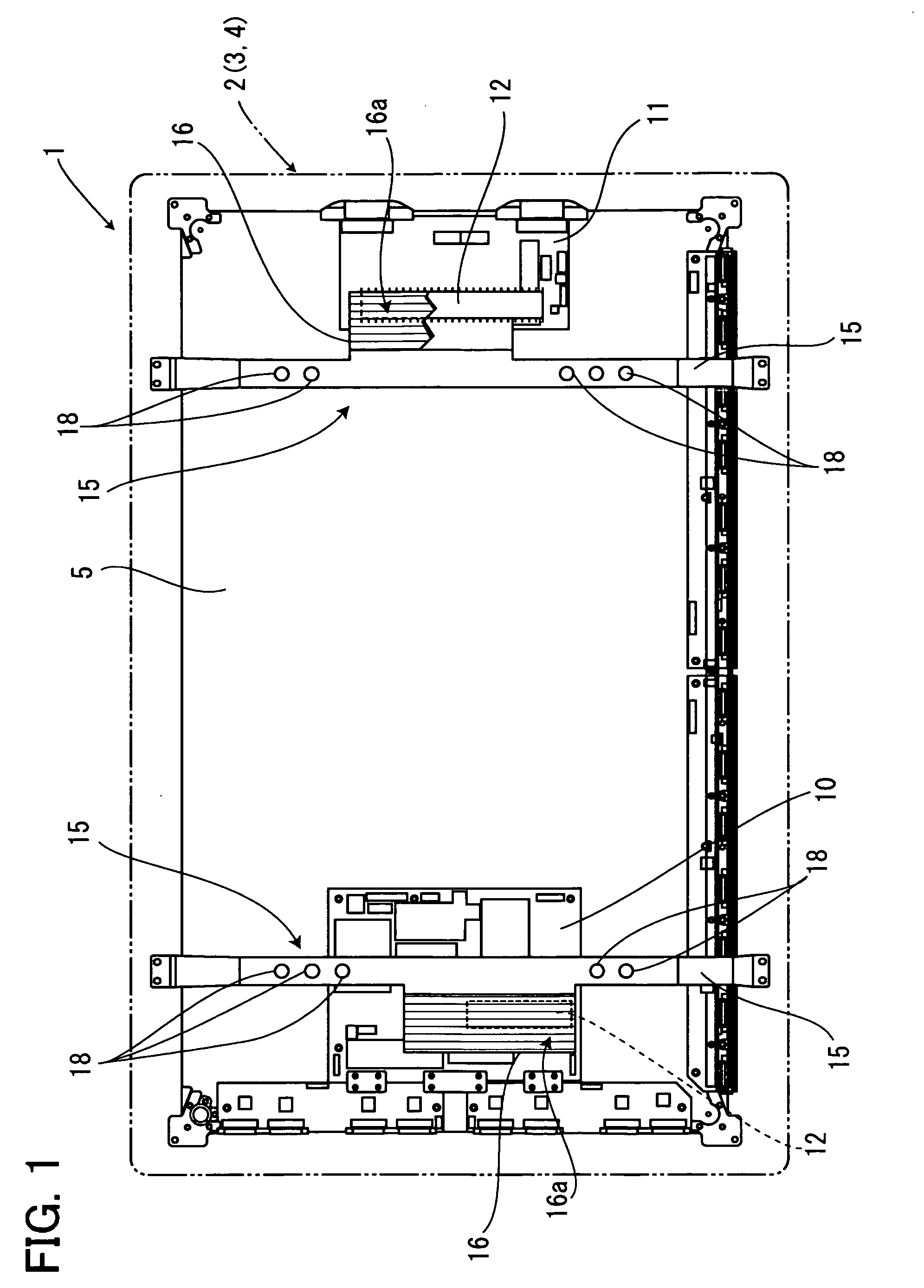
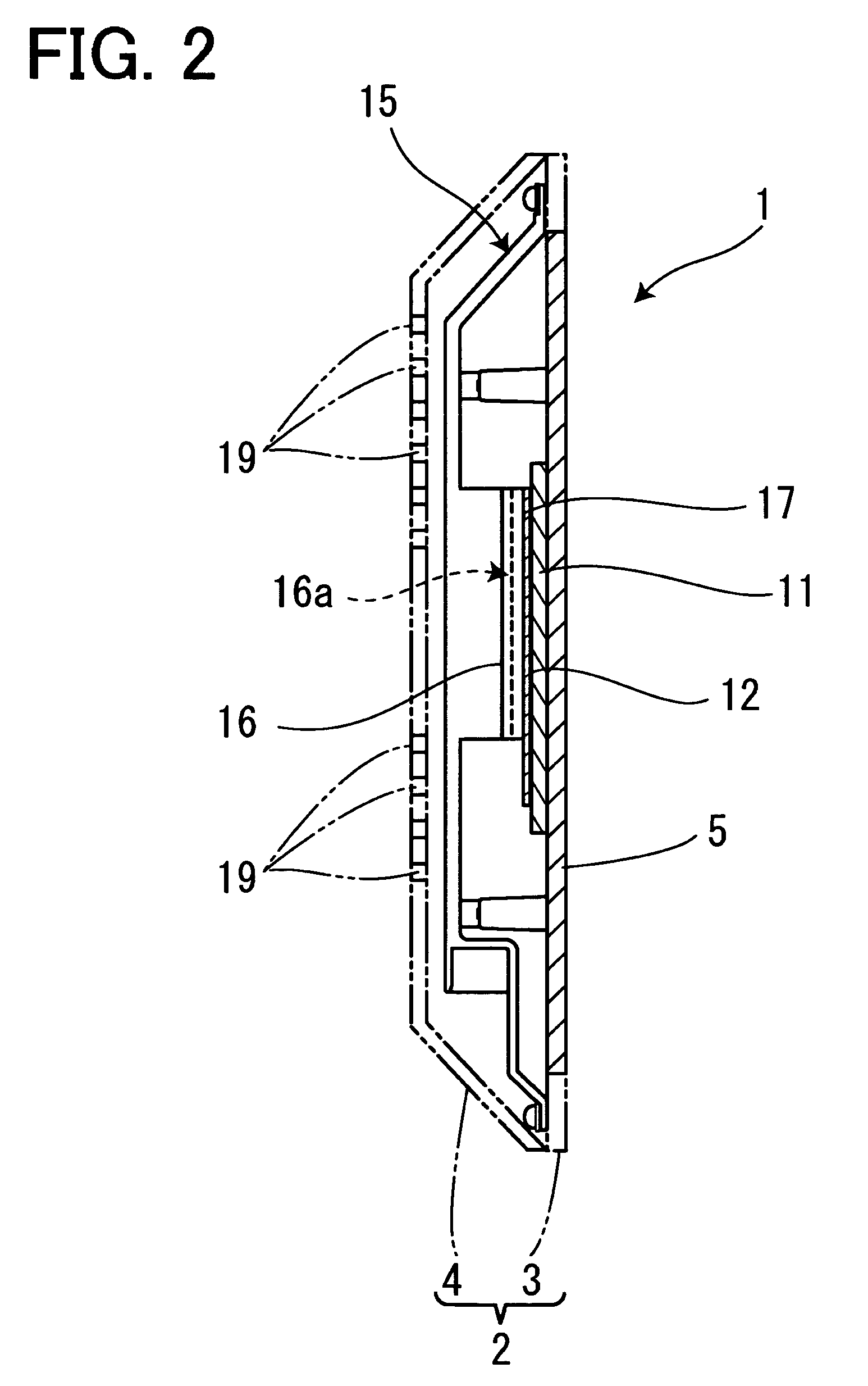
[0024]FIG. 1 is a rear view of a display device showing an example of the present invention with an enclosure removed, FIG. 2 is a sectional view of the display device viewed from the right side, FIG. 3 is a perspective view showing a reinforcement support member attached to the enclosure and FIG. 4 is a perspective view showing a modification example of the reinforcement support member.

[0025] An enclosure 2 made of resin of a PDP (Plasma Display Panel) device 1 which is the display device according to this embodiment is constructed of a front cabinet 3 and a back cabinet 4 combined as one unit and a display panel 5 which displays videos is f...


PUM


Abstract

A display device provided with a radiating structure for cooling heat of heat generating parts is provided. In a PDP device provided with a display panel which displays videos, reinforcement support members which reinforce the display panel fixed to an enclosure is made to contact heat generating parts which are heated in the enclosure and the reinforcement support members are made to have a dual-function as radiating members for radiating heat from the heat generating parts. This makes it possible to cool heat of the heat generating parts and suppress an increase in the number of parts and an increase in the manufacturing cost.

Description

[0001] The present application is based on and claims priority of Japanese patent application No. 2005-346757 filed on Nov. 30, 2005, the entire contents of which are hereby incorporated by reference. BACKGROUND OF THE INVENTION [0002] 1. Field of the Invention [0003] The present invention relates to a display device provided with a radiating structure, and more particularly, to a display device provided with a radiating structure for radiating heat from heat generating parts disposed inside a plasma display (PDP: Plasma Display Panel) device which is a display device and a PDP device provided with a radiating structure. [0004] 2. Description of the Related Art [0005] A feature of a PDP device which is in use in recent years is that it generally has a large-screen display panel to display videos and a low-profile structure, that is, a small depth compared to its overall size. A typical product of such a low-profile display device is a liquid crystal television or the like, and in re...

Claims


Application Information

Patent Timeline
Patent Type & Authority Applications(United States)
IPC IPC(8): H05K7/20
CPCH05K7/20963
Inventor UCHIZONO, TATSUYATAJIMA, KOICHI
Owner ORION ELECTRIC CO LTD
Why Eureka
Try Eureka