White light-emitting device using fluorescent fiber
a light-emitting device and fluorescent fiber technology, applied in the direction of fibre light guides, lighting and heating apparatus, instruments, etc., can solve the problems of reducing and achieve the effect of enhancing the efficiency of utilizing light and suppressing the generation of optical coupling loss
- Summary
- Abstract
- Description
- Claims
- Application Information
AI Technical Summary
Benefits of technology
Problems solved by technology
Method used
Image
Examples
first embodiment
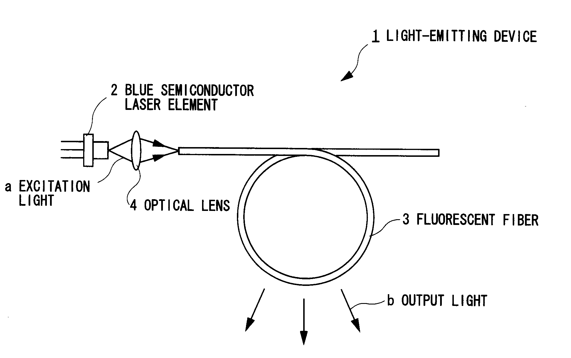
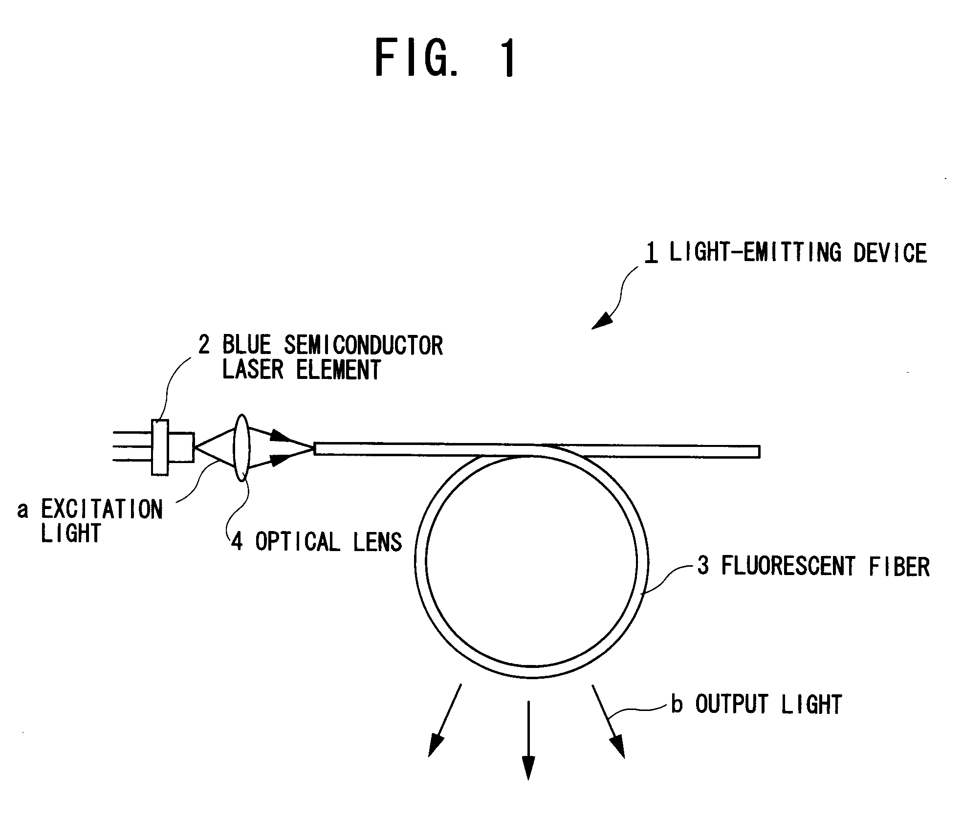
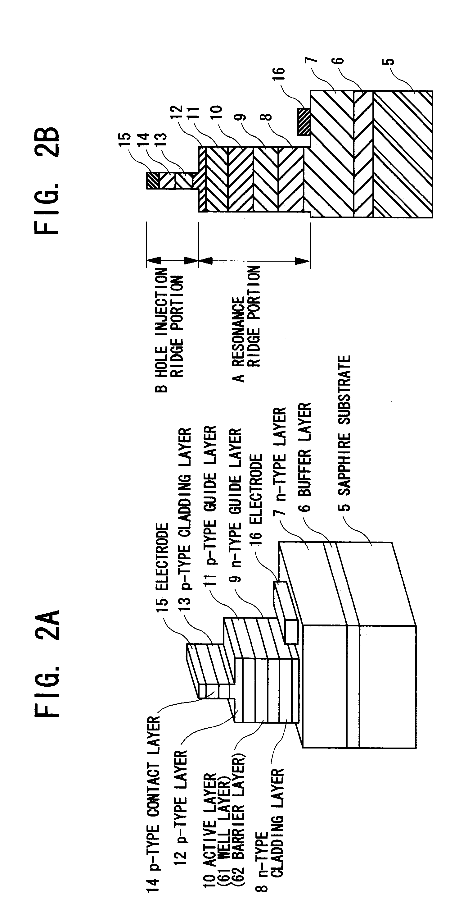
[0019]FIG. 1 is a plan view for explaining a white light-emitting device using a fluorescent fiber according to a first embodiment of the present invention, FIGS. 2A and 2B are respectively a perspective view and a cross sectional view for explaining a blue semiconductor laser element of the light-emitting device according to the first embodiment of the present invention, and FIG. 3 is a cross sectional view for explaining the fluorescent fiber of the white light-emitting device using a fluorescent fiber according to the first embodiment of the present invention.
[Overall Construction of Light-Emitting Device 1]
[0020] Referring to FIG. 1, a light-emitting device 1 roughly includes a blue semiconductor laser element 2 as an excitation light source, a fluorescent fiber 3 through which optically multiplexed lights obtained by optically multiplexing an excitation light (blue light) “a” radiated from the blue semiconductor laser element 2, and wavelength conversion lights obtained throu...
second embodiment
[0038]FIG. 5 is a cross sectional view for explaining a fluorescent fiber of a light-emitting device according to a second embodiment of the present invention.
[0039] As shown in FIG. 5, the feature of the light-emitting device (as shown in FIG. 1) 1 shown in the second embodiment is that the light-emitting device 1 includes a fluorescent fiber 50 having a core 50A, a cladding member 50B including a first cladding member 50B-1 which is formed adjacently to the peripheral surface of the core 50A, and a second cladding member 50B-2 which is formed adjacently to a peripheral surface of the first cladding member 50B-1, and a core member 50C.
[0040] For this reason, a refractive index n1 of the first cladding member 50B-1 is set to one (n1≈1.48) that is smaller than that n2 (n2≈1.50) of the core 50A, but is larger than that n3 (n3≈1.45) of the second cladding member 50B-2.
[0041] According to the second embodiment as has been described so far, in addition to the effects (1) to (3) of the...
PUM
| Property | Measurement | Unit |
|---|---|---|
| wavelength | aaaaa | aaaaa |
| wavelength | aaaaa | aaaaa |
| thickness | aaaaa | aaaaa |
Abstract
Description
Claims
Application Information
 - R&D
- Intellectual Property
- Life Sciences
- Materials
- Tech Scout
- Unparalleled Data Quality
- Higher Quality Content
- 60% Fewer Hallucinations
Browse by: Latest US Patents, China's latest patents, Technical Efficacy Thesaurus, Application Domain, Technology Topic, Popular Technical Reports.
© 2025 PatSnap. All rights reserved.Legal|Privacy policy|Modern Slavery Act Transparency Statement|Sitemap|About US| Contact US: help@patsnap.com


