Signal processor for use with a power amplifier in a wireless circuit

a technology of signal processor and power amplifier, which is applied in the direction of amplifier modification to reduce non-linear distortion, gain control, transmission, etc., can solve the problems of reducing power efficiency, significant distortion, and power amplifiers typically dominating the power consumption of these terminals

Inactive Publication Date: 2007-05-31
KK TOSHIBA
View PDF1 Cites 80 Cited by
  • Summary
  • Abstract
  • Description
  • Claims
  • Application Information

AI Technical Summary

Benefits of technology

[0023] Preferably, the output terminal of said envelope processing means is connected to said control terminal of said RF switch

Problems solved by technology

Power amplifiers typically dominate the power consumption of these terminals.
In order to increase power efficiency, amplifiers need to be driven close to their saturation region, where they have a tendency to non-linearity and there may be significant levels of distortion.
Distortion can be reduced by backing off the amplifier from saturation, but this reduces the power efficiency.
Therefore, power amplifiers are typically operated in class-A or class-AB configuration, which also implies low efficiency.
Other classes of power amplifiers, such as class B power amplifiers, show high efficiency but are often not suitable for linear applications.
However, one of the major drawbacks of implementing an EER transmitter is that it can only be implemented for narrowband applications.
This is generally due to the limited bandwidth and low frequency operation of the class-S amplifier stage.
Another disadvantage of implementing an EER transmitter is that it cannot be implemented for high peak-to-mean ratio (PMR) communication standards such as wireless local area network (WLAN).
This is because high PMR signals require the supply voltage of the power amplifier to be modulated over a large dynamic range which introduces non-linearity.
However, this method suffers a drawback, in that with the current technology it is difficult to digitise an RF signal.

Method used


Image

  • Signal processor for use with a power amplifier in a wireless circuit
  • Signal processor for use with a power amplifier in a wireless circuit
  • Signal processor for use with a power amplifier in a wireless circuit

Examples


Embodiment Construction

[0045] A method and apparatus for processing signals prior to amplification is disclosed. In the following description, a number of specific details are presented in order to provide a thorough understanding of embodiments of the present invention. It will be apparent, however, to a person skilled in the art that these specific details need not be employed to practice the present invention.

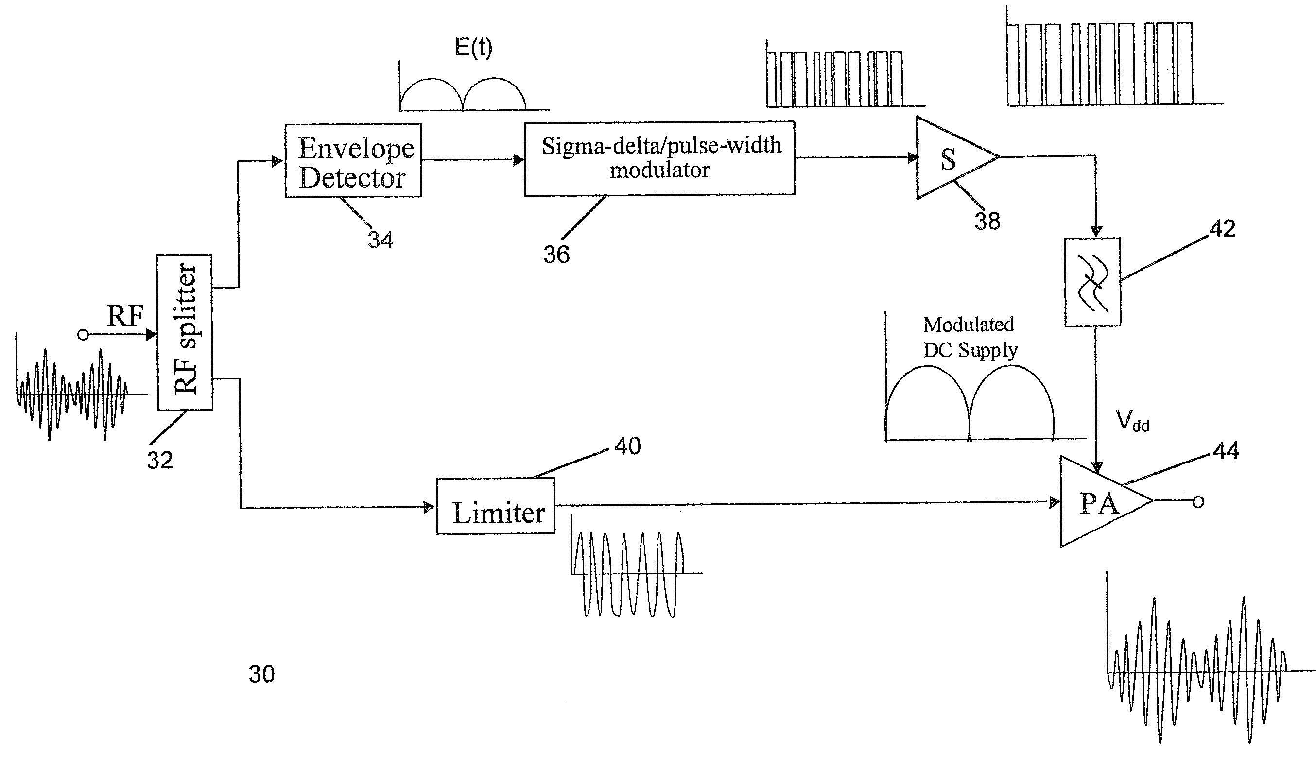
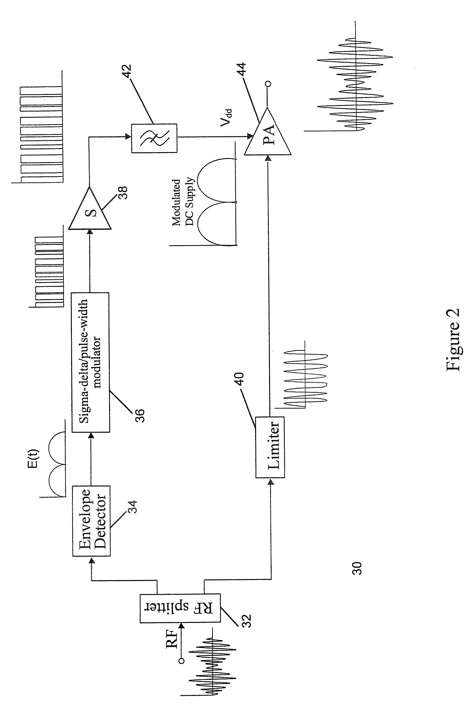
[0046]FIG. 5 shows a circuit diagram of an RF amplifier 100 comprising a signal processor 80 according to an embodiment of the present invention. Referring to FIG. 5, the signal processor 80 comprises a splitter 82, envelope detector 84, sigma-delta / pulse-width modulator 86, limiter 88 and RF switch 90. The output terminals of the splitter 82 are connected to the envelope detector 84 and the limiter 88. The envelope detector 84 is, in turn, connected to the sigma-delta / pulse-width modulator 86. The output terminal of the sigma-delta / pulse-width modulator 86 is connected to the control terminal of...


PUM


Abstract

A signal processor has an input terminal and an output terminal for use in a wireless transmitter, for generating a radio frequency signal suitable for transmission, either with or without further power amplification. The signal processor separates an input signal into first and second processing paths, the first processing path generating a pulse train signal which is a digitised envelope signal, and the second processing path comprising phase processing means operable to generate a constant envelope phase signal. An RF switch is operable to switch the phase signal by means of the pulse train signal.

Description

FIELD OF THE INVENTION [0001] The present invention generally relates to a signal processor for use with a power amplifier in a wireless circuit. BACKGROUND OF THE INVENTION [0002] A signal in a transmitter undergoes a number of stages, such as modulation, up conversion and amplification, before actually being transmitted. A transmitter in a wireless circuit usually comprises a variety of circuit elements such as frequency mixer, local oscillator, power amplifiers, filters and antennas. [0003] With reference to FIG. 1, a block circuit diagram of a conventional transmitter 10 is shown. The conventional transmitter 10 in FIG. 1 includes a baseband source 12, an up-converter (comprising a local oscillator 14 and a mixer 16), a power amplifier chain 18 and an antenna 20. In the transmitter circuit 10, the baseband source 12 produces an intermediate frequency (IF) signal. The IF signal is provided to the up-converter, which converts the IF signal to a radio frequency (RF) signal. The RF ...

Claims


Application Information

Patent Timeline
Patent Type & Authority Applications(United States)
IPC IPC(8): H04B1/04
CPCH03F1/02H03F1/0205H03F1/0222H03F1/0233H03F1/32H03F1/3282H03F3/24H03F2200/102H03F2200/331H03F2200/351H03F2200/36H03F1/3247
Inventor NESIMOGLU, TAYFUNMORRIS, KEVIN A.
Owner KK TOSHIBA
Why Eureka
Try Eureka