Ignition apparatus having conductive plastic ignition terminal and field smoother
- Summary
- Abstract
- Description
- Claims
- Application Information
AI Technical Summary
Benefits of technology
Problems solved by technology
Method used
Image

Examples
first embodiment
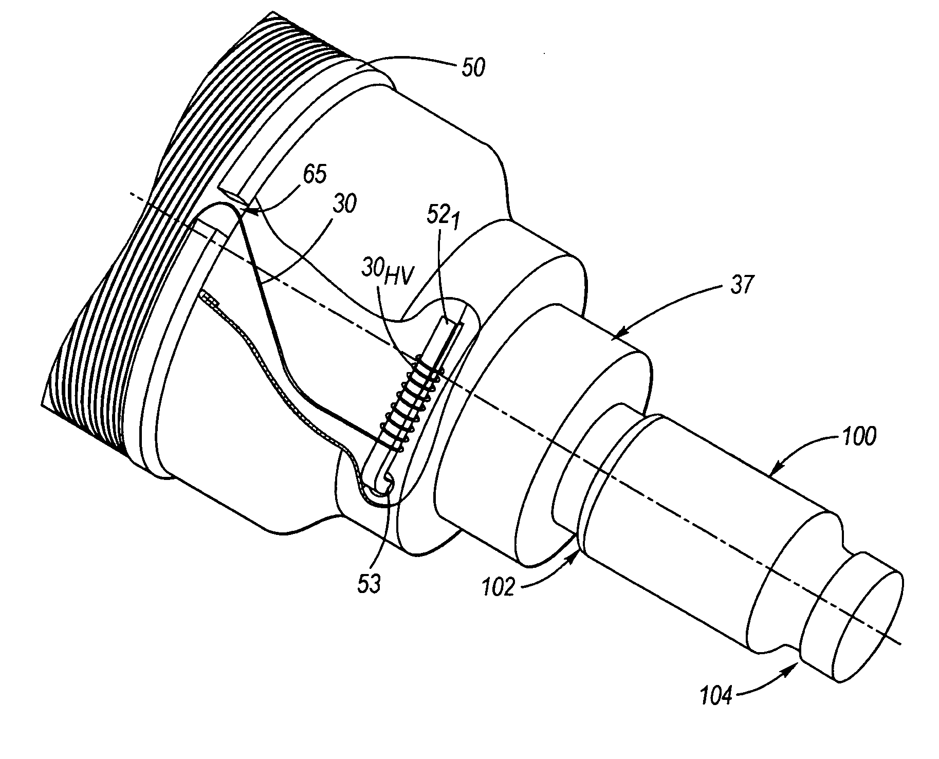
[0023]FIG. 2 is a simplified perspective view of an ignition apparatus 10 according to the invention, including a resistive element 100 formed of an electrically conductive plastic material. Resistive element 100 includes a first axial end 102 and a second axial end 104 opposite the first axial end 102. The configuration of resistive element 100 is such that it exhibits a predetermined electrical resistance suitable for suppression of electromagnetic interference. With respect to such electrical characteristics, element 100 may have the same such characteristics as resistor 41 in FIG. 1. Further, since element 100 carries the spark voltage, it is formed so that all curves / transitions and outer surfaces are smooth and of relatively large radii so as to reduce any electric field concentration.
[0024] Resistive element 100 may comprise polymers suitable for injection molding, such as polyethylene terephthalate (PET), polybutylene terephthalate (PBT) or various nylon materials (e.g., nyl...
case 34
[0047] Case 34 includes an inner, generally enlarged cylindrical surface, an outer surface, a first annular shoulder, a flange, an upper through-bore, and a lower through bore.
[0048] The inner surface of case 34 is configured in size to receive and retain spool 28 which contains the core 16 and primary winding 24. The inner surface of case 34 may be slightly spaced from spool 28, particularly the annular features 48, 50 thereof (as shown), or may engage the features 48, 50.
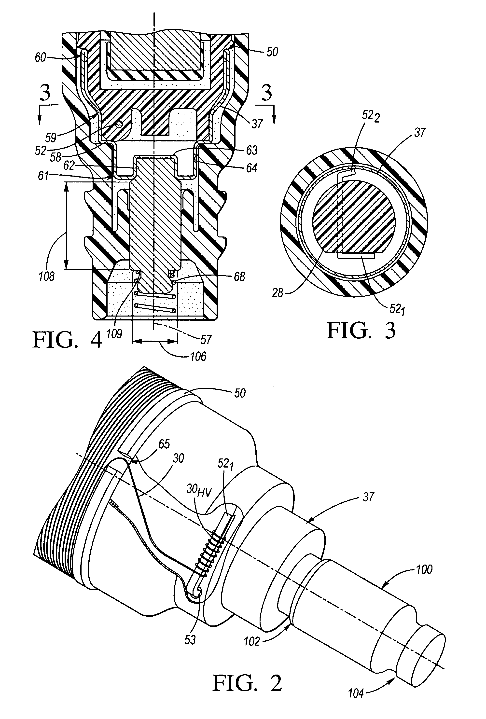
[0049] Lower through-bore 64 (best shown in FIG. 4) is defined by an inner surface thereof configured in size and shape (i.e., generally cylindrical) to accommodate an outer surface of cup 37 (or cup portion 37 in the alternate embodiment of FIG. 5) at a lowermost portion thereof as described above. When the lowermost body portion of spool 28 is inserted in the lower bore containing cup 37 (or cup portion 37), a portion of HV terminal 522 engages an inner surface thereof (also via a press fit).
[0050] Case 34 is ...
second embodiment
[0054] Cup portion 37′ of element 110 (FIG. 5), in the second embodiment, is generally the same as cup 37′, except that it is integral with resistive element portion 100′ and formed of conductive plastic material. In this regard, the nature of the curves and transitions may exhibit even somewhat larger radii than with cup 37.
[0055] Low voltage connector body 38 via module 22 is configured to, among other things, electrically connect the first and second ends of primary winding 24 to an energization source, such as, the energization circuitry (e.g., power source) included in ignition system 12. Connector body 38 is generally formed of electrical insulating material, but also includes a plurality of electrically conductive output terminals 66 (e.g., pins for ground, primary winding leads, etc.). Terminals 66 are coupled electrically, internally through connector body 38 to module 22 and other portions of apparatus 10, in a manner known to those of ordinary skill in the art.
[0056] HV ...
PUM
 Abstract
Description
Claims
Application Information
 - Generate Ideas
- Intellectual Property
- Life Sciences
- Materials
- Tech Scout
- Unparalleled Data Quality
- Higher Quality Content
- 60% Fewer Hallucinations
Browse by: Latest US Patents, China's latest patents, Technical Efficacy Thesaurus, Application Domain, Technology Topic, Popular Technical Reports.
© 2025 PatSnap. All rights reserved.Legal|Privacy policy|Modern Slavery Act Transparency Statement|Sitemap|About US| Contact US: help@patsnap.com