Photoelectric converter and method for manufacturing same

Inactive Publication Date: 2007-06-07
THE FUJIKURA CABLE WORKS LTD
View PDF6 Cites 27 Cited by
  • Summary
  • Abstract
  • Description
  • Claims
  • Application Information

AI Technical Summary

Benefits of technology

[0045] The above manufacturing method particularly includes the steps of directly or indirectly providing the counter electrode on the inner bottom surface of the housing body constituting the casing; overlaying the working electrode on the counter electrode so that the counter electrode contacts the electrolyte layer to form a stacked body; placing the working electrode so that it functions as the lid body of the casing; and sealing the working electrode to the housing body using a laser method or an adhesion method to fabricate the casing. Thus, it is possible to easily perform the sealing by radiating a laser on (referred to as a laser method) or providing an adhesive (referred to as an adhesion method) to the portion to be sealed without using conventionally used resins. In other words, the sealing is performed by radiating a laser on or bonding only the connecting portion between the lid body and the housing body in the manufacturing

Problems solved by technology

However, conventional silicon-based solar cells have not been in common use since there are problems to be solved, such as expensive manufacturing costs and insufficient supply of raw materials.
However, such compound solar cells have not become widespread due to problems, such as costs and environmental load.
However, the above-described dye-sensitized solar cell has a problem in that a volatile solvent, such as acetonitrile, is used in the electrolyte solution that is sealed in the cell and the cell performances may be deteriorated due to volatilization in such a system.
Furthermore, since an electrolyte solution, when used, may leak during the manufacturing processes or upon breakage of the cell, attempts have been made by various research institutions in order

Method used


Image

  • Photoelectric converter and method for manufacturing same
  • Photoelectric converter and method for manufacturing same
  • Photoelectric converter and method for manufacturing same

Examples


first embodiment

[0073] A first embodiment of the present invention will be described in detail based on examples.

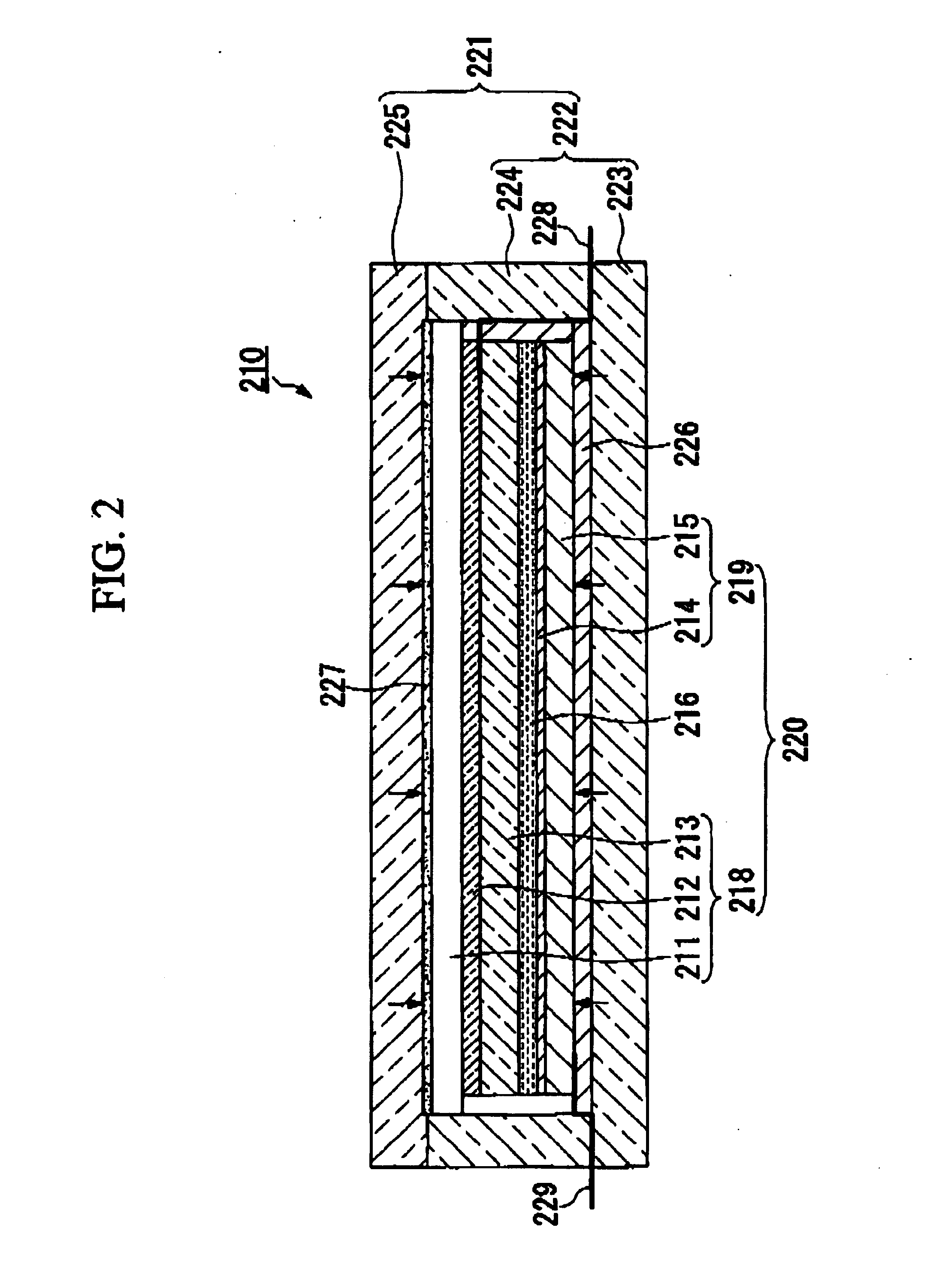
[0074]FIG. 2 is a schematic cross-sectional view illustrating an example of a photoelectric conversion element according to a first embodiment of the present invention.

[0075] A dye-sensitized solar cell (photoelectric conversion element) 210 includes a working electrode (also referred to as a window electrode) 218 having a porous oxide semiconductor layer (also referred to as an oxide electrode) 213 having a sensitizing dye supported on the surface thereof, a counter electrode 219 provided on the porous oxide semiconductor layer 213 side of the working electrode 218 facing to the porous oxide semiconductor layer 213, and an electrolyte layer 216 at least a part of which is between the two electrodes. The working electrode 218 includes, for example, a first substrate 211 and a transparent conductive film 212 and an oxide electrode 213 provided thereabove in this order. The opposing coun...

second embodiment

[0101] In the above, a photoelectric conversion element 250 according to the first embodiment of the present invention as shown in FIG. 4 has been described. Improvements are made for this photoelectric conversion element 250 mainly from the following two viewpoints.

[0102] Firstly, the influence on dye supported on a dye-sensitized semiconductor electrode caused by the heat applied when electrodes are bonded together is reduced, excellent weather resistance when used for a long time is provided, and the injection of an electrolyte solution is facilitated.

[0103] In other words, according to the structure shown in FIG. 4, since the heat is not directly applied to two electrodes, i.e., a working electrode 258 and a counter electrode 259, it is possible to eliminate the influence of the heat on the above-described dye. Furthermore, it is possible to form a stacked body 260 formed by sandwiching the electrolyte solution between the working electrode 258 and the counter electrode 259 by...

third embodiment

[0139] A third embodiment of the present invention will be described in detail based on examples.

[0140]FIG. 6 is a plan view illustrating a dye-sensitized solar cell as an example of a photoelectric conversion element according to a third embodiment of the present invention, and FIG. 7 is a cross-sectional view taken along Line A-A in FIG. 6.

[0141] A dye-sensitized solar cell 401 is formed by arranging and sealing a plurality of stacked bodies 402 on a single plane within a casing 403.

[0142] The stacked body 402 is formed by stacking a working electrode 421 having a porous oxide semiconductor layer 421a provided on one surface thereof, a counter electrode 422 provided opposing the porous oxide semiconductor layer 421a, and an electrolyte layer (not shown) between the working electrode 421 and the counter electrode 422 together.

[0143] The working electrode 421 includes a transparent substrate 421b that is a glass substrate, a light-transmitting plastic film, or the like, a transp...


PUM


Abstract

A photoelectric conversion element is provided. The photoelectric conversion element includes a casing; and a stacked body enclosed within the casing, wherein the stacked body comprises: a working electrode having a porous oxide semiconductor layer having a sensitizing dye supported on a surface thereof; a counter electrode provided on a side of the porous oxide semiconductor layer of the working electrode facing the working electrode; and an electrolyte layer at least a part of which is formed between the working electrode and the counter electrode, and wherein an upper surface and a lower surface of the stacked body contacts directly or indirectly an inner surface of the casing, the portion of the casing at least contacting the working electrode being made of a material having an optical characteristic of transmitting sunlight.

Description

[0001] Priority is claimed on Japanese Patent Application No. 2003-288076 filed Aug. 6, 2003; Japanese Patent Application No. 2003-421084 filed Dec. 18, 2003; Japanese Patent Application No. 2003-430606 filed Dec. 25, 2003; Japanese Patent Application No. 2004-63032 filed Mar. 5, 2004; Japanese Patent Application No. 2004-106616, filed Mar. 31, 2004; and Japanese Patent Application No. 2004-106617 filed Mar. 31, 2004, the contents of which are incorporated herein by reference.TECHNICAL FIELD [0002] The present invention relates to a photoelectric conversion element, such as a dye-sensitized solar cell, and a method for manufacturing the same. More specifically, the present invention relates to a photoelectric conversion element in which a cell constituting member and a packaging material provided outside the cell constituting member can be sealed as a whole without applying any load, such as application of heat, on a cell having a stacked body formed by sandwiching an electrolyte la...

Claims


Application Information

Patent Timeline
IPC IPC(8): H01L31/00H01G9/20H01M14/00
CPCH01G9/2031H01G9/2077H01M14/005Y02E10/542Y02P70/50H01M14/00H01L31/04
Inventor EZURE, TETSUYATANABE, NOBUOMATSUI, HIROSHIOKADA, KENICHI
Owner THE FUJIKURA CABLE WORKS LTD
Why Eureka
Try Eureka