Frame for heavy-duty vehicles

a technology for heavy-duty vehicles and frames, applied in the field of frames and subframes for heavy-duty vehicles, can solve the problems of bending loads, affecting the operation of heavy-duty vehicles, and containing more than one non-steerable axle, and reducing the damage to the main member and/or other components, reducing the damage, and reducing the damag

Inactive Publication Date: 2007-06-07
HENDRICKSON USA L L C
View PDF12 Cites 35 Cited by
  • Summary
  • Abstract
  • Description
  • Claims
  • Application Information

AI Technical Summary

Benefits of technology

[0016] An objective of the present invention is to provide a frame or subframe for a heavy-duty vehicle having a discrete component that absorbs the energy created by single-wheel impacts or static hang-ups, thereby reducing damage to the main members and / or other components of the frame or subframe caused by such an event.
[0017] Another objective of the present invention is to provide an easier, more efficient and cost-effective method of repairing a heavy-duty vehicle frame or subframe that has been subjected to a severe single wheel impact or static hang-up
[0018] Yet another objective of the present invention is to provide a frame or subframe for a heavy-duty vehicle having an optimal connection between the hangers and the main members when lightweight materials awe used.
[0019] These objectives and advantages are obtained by the frame for a heavy-duty vehicle of the present invention. In an exemplary embodiment of the invention, the frame includes a pair of spaced-apart, parallel, elongated, and longitudinally-extending main members. A pair of transverse cross members extend between and are attached to the main members, and each one of at least a pair of hangers is attached to and depends from a respective one of the main members for suspending an axle / suspension system from the frame. Means for absorbing energy created by an extreme event during vehicle operation minimizes damage to at least one of the main members and the cross members which is caused by movement of at least one of the hangers during the extreme event

Problems solved by technology

More particularly, heavy-duty vehicles, such as tractortrailer's, which contain more than one non-steerable axle are subject to lateral or side loads during vehicle operation.
Lateral loads can act through the slider box in opposite directions, which in turn may create bending loads, the effect of which can be significant.
Moreover, a slider box is often subjected to strong vertical and longitudinal loads.
When a vehicle encounters an extreme event, vertical and horizontal crush forces are produced that potentially can cause significant damage to the slider box.
A side force may also be produced if the impact is on a single wheel, which may cause the beam of the axle / suspension system to pull back and sideways, potentially causing the hanger to twist.
These impacts could damage, or in an extreme case, cause the slider box main member and / or one or more of the attached cross members to fail, in either instance eventually requiring replacement, which is costly and time-consuming.
This design of a typical slider tandem causes many vehicles containing such slider tandems, including semi-trailers and tractortrailers, to be out of service for extended periods of time after extreme events, such as single-wheel impacts, until the entire slider box can be replaced.
This represents a significant problem in the trucking industry.
However, certain characteristics of aluminum, such as high thermal conductivity and a low melting point, make the welding of aluminum components different, and potentially more difficult, than the welding of steel components In addition, aluminum components that are welded to one another or to a dissimilar metal, such as steel, may exhibit fatigue at the weld area, thereby potentially creating a weaker connection when compared to steel components that are welded together.
Such stress may cause a welded connection that involves a material which is not readily welded, and therefore may be less than optimal, to undesirably fail, thereby reducing the durability of the slider box.
As a result, the limited ability of prior art heavy-duty vehicle frames and subframes to absorb the energy created by extreme events without significant damage, as well as the limited ability to provide an optimal connection between the hangers and the main members when lightweight materials are used, makes it desirable to develop heavy-duty vehicle frames and subframes that overcome these disadvantages.

Method used


Image

  • Frame for heavy-duty vehicles
  • Frame for heavy-duty vehicles
  • Frame for heavy-duty vehicles

Examples


third embodiment

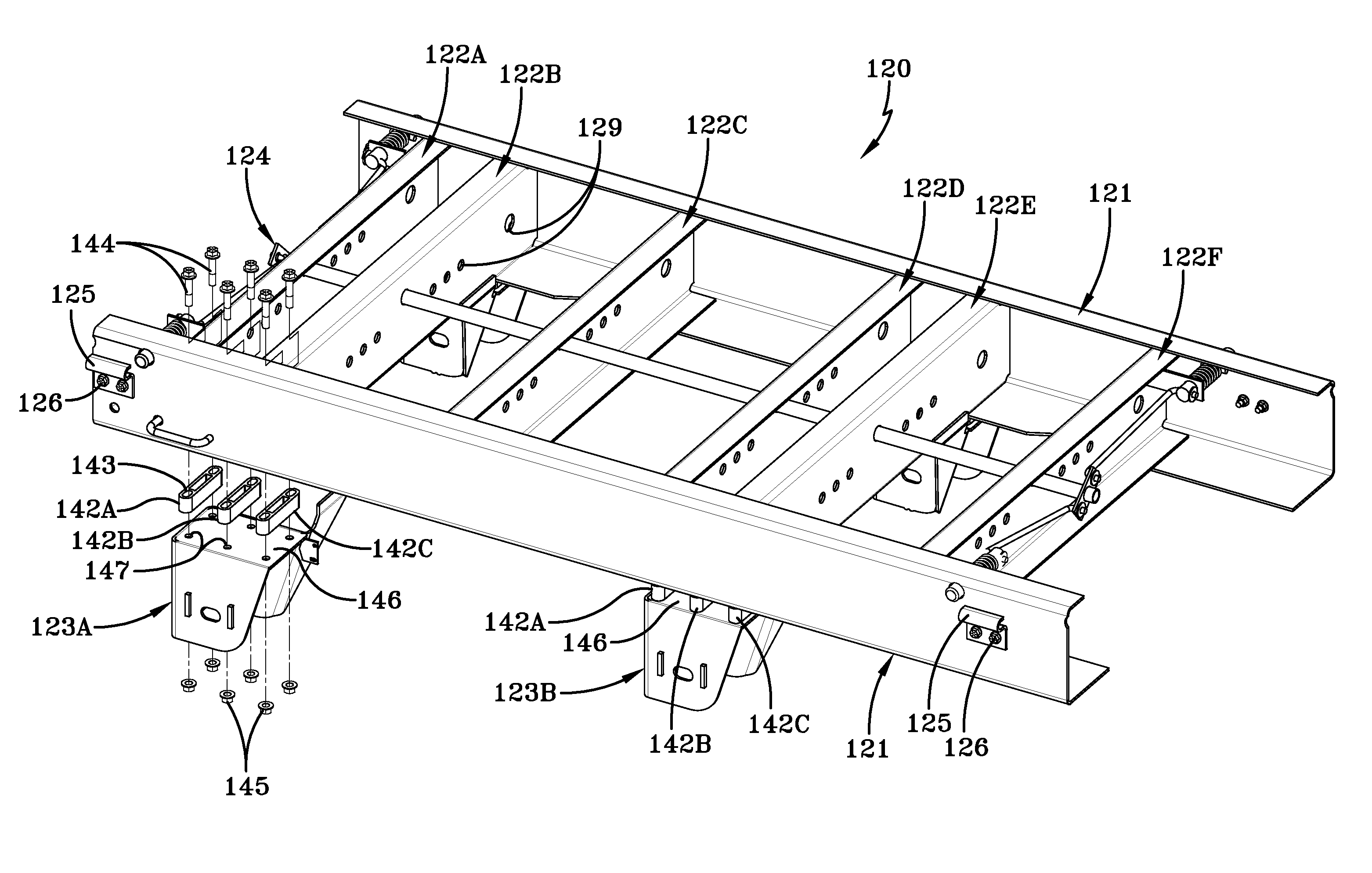
[0086] It should be noted that, in all embodiments of the present invention, certain components may be adapted to suit specific design requirements. For example, in third embodiment slider box 320, the use of spacers 342 may make it desirable to adapt hangers 123A, B for additional attachment to and reinforcement of slider box 320. Thus, a hanger extension 344, which extends inboardly from each respective hanger 123A, B and upwardly to a respective one of cross members 122C, 122E, may be used.

[0087] A fourth exemplary embodiment of the slider box of the present invention is shown in FIG. 11, is indicated generally at 420, and is an improvement over prior art slider box 20. Fourth embodiment slider box 420, as with all embodiments of the present invention, supports front and rear axle / suspension systems 130A and 130B, respectively, and thus a slider tandem is indicated generally at 439. Since many aspects of fourth embodiment slider box 420 are similar to that as described above for ...

fourth embodiment

[0092] It should be noted that one particularly preferred feature of fourth embodiment slider box 420 of the present invention is that main member sidewalls 441 (FIG. 12) possess greater tear-out strength about mounting bolt openings 445 than do hanger sidewalls 440 about their corresponding mounting bolt openings 443A. This can be accomplished, for example, by designing main member sidewalls 441 to be thicker than hanger sidewalls 440, and / or for the main member sidewalls to be made from a higher-strength grade of material than the hanger sidewalls. This minimizes the possibility that main member 421 will be damaged after such an extreme event.

[0093] Referring now to FIG. 14, slider box 420 then can be temporarily repaired by removing front mounting bolt 444A and its spacer 442, rotating hanger 423A back to its normal position, and relocating those components to auxiliary hanger openings 443B and corresponding auxiliary aligned openings 450 (FIG. 13) formed in main member sidewalls...

fifth embodiment

[0101] More particularly, each sidewall 526′ of hanger shell 524′ is formed with a series of continuous, generally round, aligned openings 541A′ and 541B′. Openings 541A′ and 541B′ extend longitudinally relative to the heavy-duty vehicle (not shown) and thereby enable sidewalls 526′ to form a tooth 570 between each successive round portion of openings 541A′, 541B′. Teeth 570 provide separation and increased load deflection when compared to smooth slots 541 of fifth embodiment hanger 523 (FIG. 15) as bolts 544A, B and hanger insert 525 move longitudinally rearwardly upon the heavy-duty vehicle encountering an extreme event. In addition, the proximity and interconnection of openings 541A′ and 541B′ provides a range of selectable positions for bolt 544 that secures hanger insert 525 to hanger shell 524′ for optimal positioning of the insert within the shell.

[0102] A seventh exemplary embodiment of the slider box of the present invention is shown in FIGS. 19 and 20, is indicated general...


PUM


Abstract

A frame for a heavy-duty vehicle includes a pail of spaced-apart, parallel, elongated, and longitudinally-extending main members. At least a pair of transverse cross members extend between and are attached to the main members, and each one of at least a pair of hangers is attached to and depends from a respective one of the main members and / or the cross members. A component is disposed between each one of the hangers and its respective main member, or alternatively is incorporated into the hangers, for absorbing the energy that is created by an extreme event during vehicle operation, to reduce the possibility of damage to the main members and / or the cross members caused by movement of at least one of the hangers during the extreme event.

Description

CROSS-REFERENCE TO RELATED APPLICATION [0001] This application claims the benefit of U.S. Provisional Patent Application Ser. No. 60 / 738,153, which was filed on Nov. 18, 2005.BACKGROUND OF THE INVENTION [0002] 1. Technical Field [0003] The invention relates to heavy-duty vehicles, and in particular to frames and subframes for heavy-duty vehicles having improved energy absorption characteristics. More particularly, the present invention is directed to frames and subframes for heavy-duty vehicles which include a component that is disposed between the suspension hangers and the main members of the frame or subframe from which the hangers depend, or is incorporated into the hangers, and which absorbs energy that is created by a single-wheel impact or by a wheel becoming restrained in service, thereby reducing the possibility of damage to the hangers or the members of the frame or subframe caused by such an event. [0004] 2. Background Art [0005] Heavy-duty vehicles that transport cargo, ...

Claims


Application Information

Patent Timeline
Patent Type & Authority Applications(United States)
IPC IPC(8): B62D21/00
CPCB60G7/02B60G2200/31B60G2200/4622B60G2204/143B60G2204/15B60G2204/4302B60G2204/4402B60G2204/61B60G2206/0114B60G2206/601B60G2206/722B60G2206/8101B60G2206/8105B60G2206/911B60G2300/0262B60G2300/04B60G2300/40B60G2500/30B62D21/02B62D33/00B60G2206/71
Inventor RAMSEY, JOHN EDWARDMORRIS, BRIAN RICHARDOYSTER, MICHAEL D.COPELAND, GREG
Owner HENDRICKSON USA L L C
Why Eureka
Try Eureka