Multi-modulation frequency laser range finder and method for the same

a laser range finder and multi-modulation technology, applied in the direction of distance measurement, instruments, surveying and navigation, etc., can solve the problems of complicated circuits, large errors, and limited phase-shift measurement methods in distance measuremen

Inactive Publication Date: 2007-06-07
CHEN SU LIN +1
View PDF3 Cites 34 Cited by
  • Summary
  • Abstract
  • Description
  • Claims
  • Application Information

AI Technical Summary

Benefits of technology

[0011] Another object of the present invention is to make use of the under sampling theory so that the sampling frequency won't chan

Problems solved by technology

Because phase is periodic with a modulo of 2π, the phase-shift measurement method is limited in the measurement of distance.
Moreover, because two PLLs and two mixers are used in the circuit, the cir

Method used


Image

  • Multi-modulation frequency laser range finder and method for the same
  • Multi-modulation frequency laser range finder and method for the same
  • Multi-modulation frequency laser range finder and method for the same

Examples


Embodiment Construction

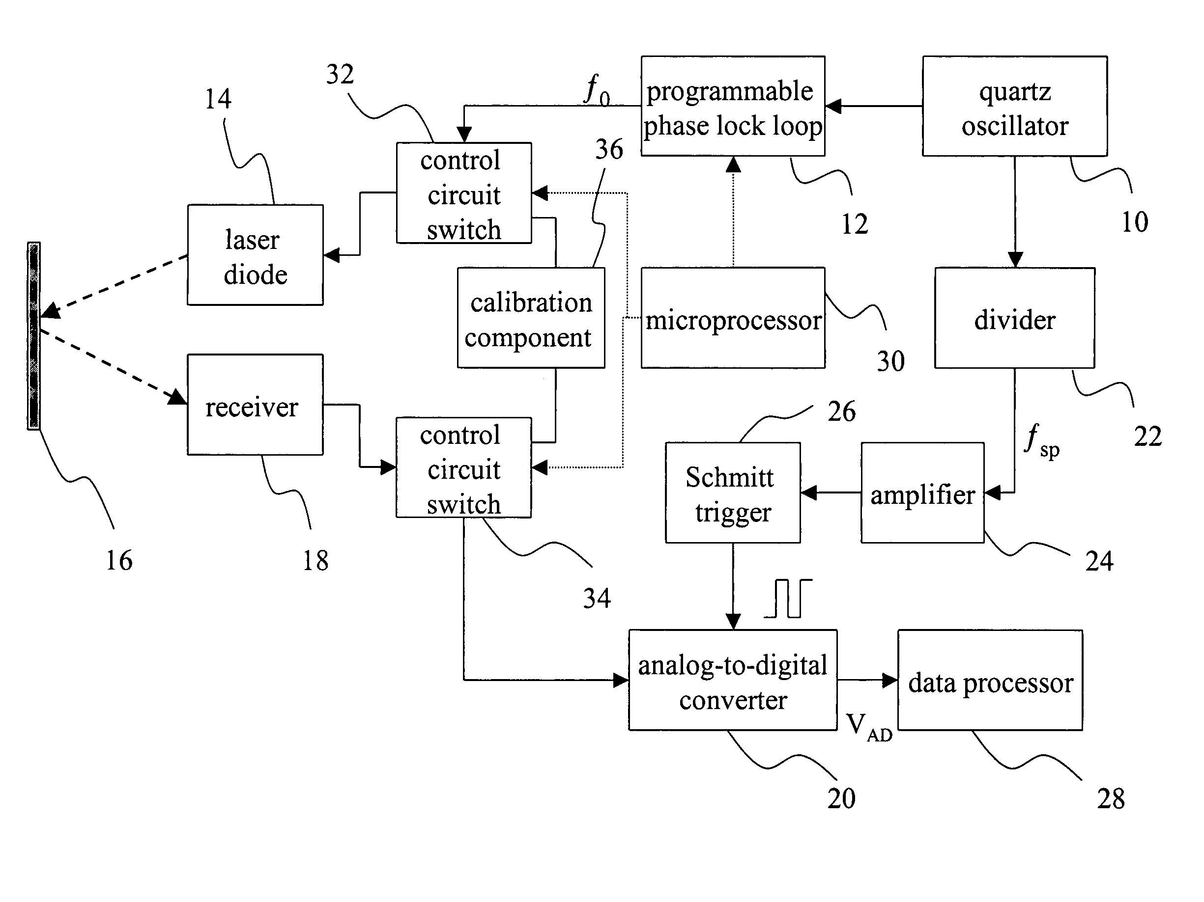
[0019]FIG. 3 is a block diagram of the present invention. As shown in FIG. 3, a quartz oscillator 10 is used as a frequency generator, which sends out a modulation signal and a sampling signal and ensures initial phases of these two signals are locked. The modulation signal passes a programmable PLL 12 to have a frequency f0. The sampling signal passes a divider 22 to get a lower sampling frequency fsp. The modulation signal then passes a circuit switch 32. Because the circuit switch has not been activated yet, the modulation signal is immediately sent to a laser diode 14 without any change. The modulation signal drives the laser diode 14 to produce a laser light beam emitted to a target 16.

[0020] This beam is reflected by the target 16 and then received by an optical receiver (not shown) in a receiver 18. The receiver 18 demodulates the laser light beam into a reception signal. Next, the reception signal is transmitted by a non-activated circuit switch 34 to an analog-to-digital c...


PUM


Abstract

A multi-modulation frequency laser range finder and a method for the same make use of a crystal oscillator to send out a modulation signal and a sampling signal. After the modulation signal is coupled with a light signal emitted by a laser diode, a laser light beam is generated and emitted to a target. The laser light signal is reflected by the target and received by a receiver to be converted to a reception signal, which is processed according to the frequency of the sampling signal. The processed result is finally sent to a data processor to calculate out the distance to the target. As compared to the prior art, less number of components are used, the precision is enhanced, and the circuit is much simplified, hence reducing the errors and the cost.

Description

BACKGROUND OF THE INVENTION [0001] 1. Field of the Invention [0002] The present invention relates to a range finder and a measurement method for the same and, more particularly, to a multi-modulation frequency laser range finder and a method for the same. [0003] 2. Description of Related Art [0004] Laser ranging methods can be classified into three categories: the time of flight measurement method, the phase-shift measurement method, and the triangulation method. The phase-shift measurement makes use of a laser light to illuminate a distant target, and the reflected light is received by a detector to produce an electric signal. The phase difference between this electric signal and a reference signal is calculated to obtain the distance to the target. Because phase is periodic with a modulo of 2π, the phase-shift measurement method is limited in the measurement of distance. The range of measurement is about several tens of meters, and the precision is about in the order of millimeter...

Claims


Application Information

Patent Timeline
IPC IPC(8): G01C3/08
CPCG01S7/497G01S17/36
Inventor CHEN, SU-LINGKUO, YI-TINGOU-YANG, MANGCHEN, JUNE-WEN
Owner CHEN SU LIN
Why Eureka
Try Eureka