Drive control method of electrostatic-type ultrasonic transducer, electrostatic-type ultrasonic transducer, ultrasonic speaker using electrostatic-type ultrasonic transducer, audio signal reproducing method, superdirectional acoustic system, and display

Inactive Publication Date: 2007-06-07
SEIKO EPSON CORP
View PDF7 Cites 18 Cited by
  • Summary
  • Abstract
  • Description
  • Claims
  • Application Information

AI Technical Summary

Benefits of technology

[0030] The invention has been developed so solve the above problems. It is an object of the invention to provide a push-pull-type electrostatic-type ultrasonic transduce

Problems solved by technology

However, the maximum sound pressure of the electrostatic-type ultrasonic transducer generates sound pressure of only 120 dB or lower, which is slightly insufficient when the transducer is used for an ultrasonic speaker.
Thus, distortion of the modulated waves is caused, resulting in waveform separation of the modulated waves into carrier waves (ultrasonic waves) and audio waves (original audio signals).
However, it is difficult for the electrostatic-type ultrasonic transducer to achieve this level, and thus a ceramic piezoelectric device such as PZT or a polymeric piezoelectric device such as PVDF is often used as an ultrasonic wave generator.
Thus, the frequency range where high sound pressure is securely generated is extremely narrow.
It is easily understood that accurate reproduction (demodulation) in the wide range of 20 kHz is absolutely impossible when the conventional resonance-type ultrasonic speaker having the piezoelectric device is used.
Actually, the ultrasonic speaker using the conventional resonance-type ultrasonic transdu

Method used


Image

  • Drive control method of electrostatic-type ultrasonic transducer, electrostatic-type ultrasonic transducer, ultrasonic speaker using electrostatic-type ultrasonic transducer, audio signal reproducing method, superdirectional acoustic system, and display
  • Drive control method of electrostatic-type ultrasonic transducer, electrostatic-type ultrasonic transducer, ultrasonic speaker using electrostatic-type ultrasonic transducer, audio signal reproducing method, superdirectional acoustic system, and display
  • Drive control method of electrostatic-type ultrasonic transducer, electrostatic-type ultrasonic transducer, ultrasonic speaker using electrostatic-type ultrasonic transducer, audio signal reproducing method, superdirectional acoustic system, and display

Examples


first embodiment

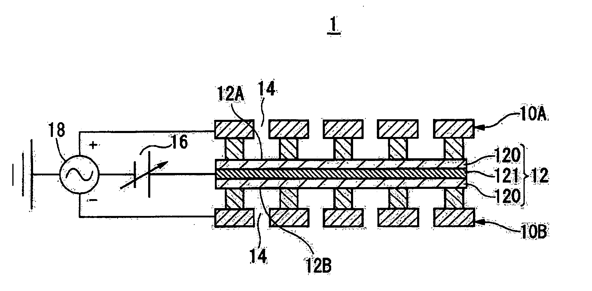
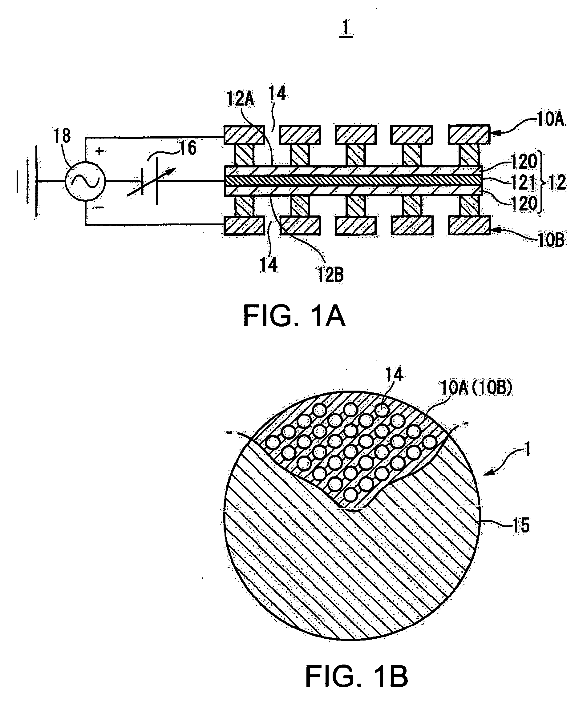
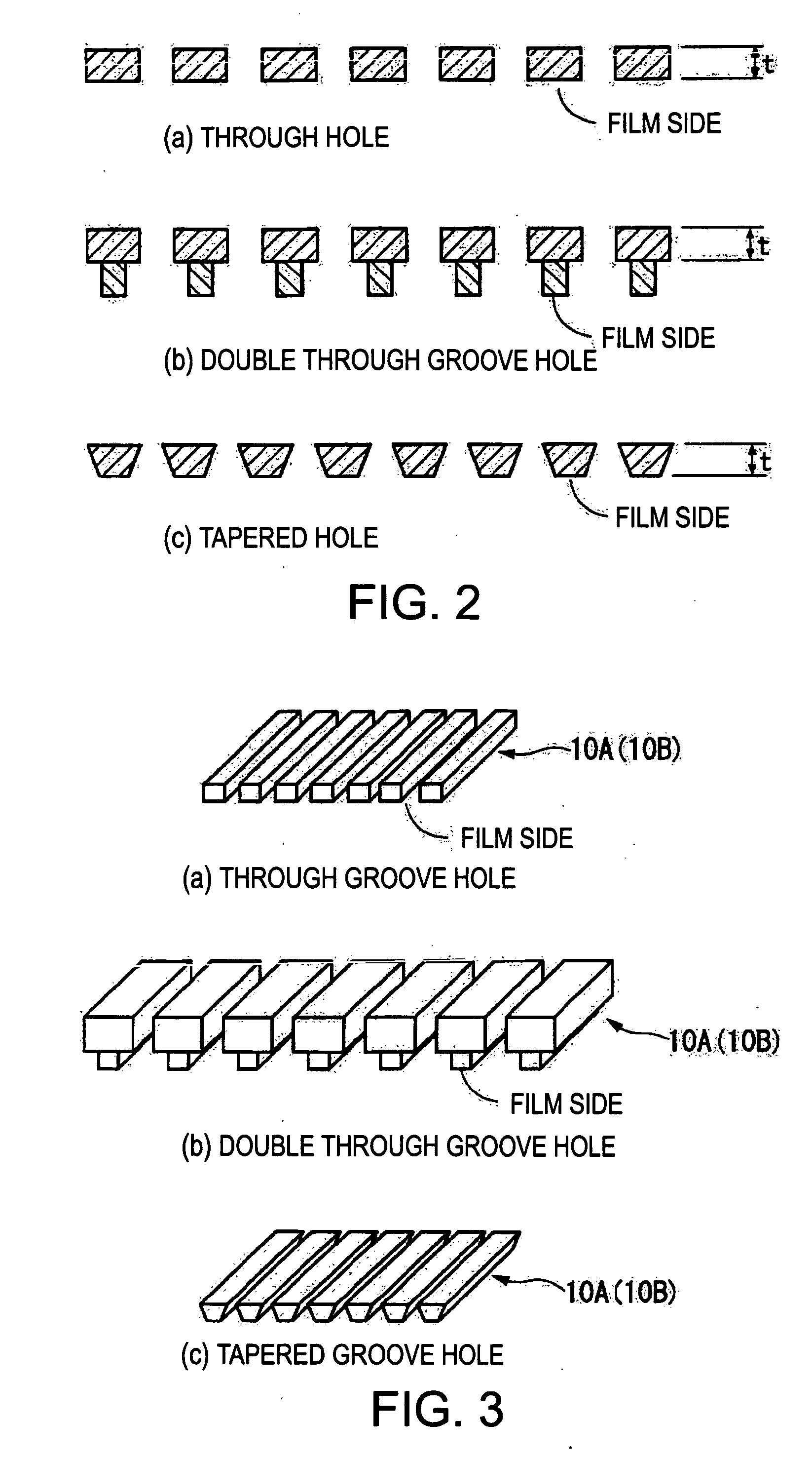
[0178] In the embodiment according to the invention (first embodiment), when the wavelength calculated from the resonance frequency as the mechanical oscillation resonance point of the oscillation film 12 in the electrostatic-type ultrasonic transducer 1 is λ, for example, the respective thicknesses t of a pair of the fixed electrodes 10A and 10B are determined as (λ / 4)·n or substantially (λ / 4)·n (where λ: wavelength of ultrasonic wave, n: positive odd number). The electrostatic-type ultrasonic transducer having this structure according to the invention has the plural through holes 14 at the opposed positions of the first fixed electrode 10A and the second fixed electrode 10B. The AC signals as operation signals are applied to a pair of the fixed electrodes constituted by the first and second fixed electrodes 10A and 10B while DC bias voltage is being applied to the conductive layer 121 of the oscillation film 12. As a result, the oscillation film 12 sandwiched between the two fixed...

second embodiment

[0189] Next, an electrostatic-type ultrasonic transducer in a second embodiment according to the invention is described. In this embodiment, a thickness t1 of one of the two fixed electrodes 10A and 10B of the electrostatic-type ultrasonic transducer 1 shown in FIG. 1 is determined as (λ / 4)·n or substantially (λ / 4)·n (where λ: wavelength of ultrasonic wave, n: positive odd number), and a thickness t2 of the other fixed electrode is determined as (λ / 4)·m or substantially (λ / 4)·m (where λ: wavelength of ultrasonic wave, m: positive even number).

[0190] The electrostatic-type ultrasonic transducer having this structure has the plural through holes 14 at the opposed positions of the first fixed electrode 10A and the second fixed electrode 10B. The AC signals as operation signals are applied to a pair of the fixed electrodes 10A and 10B constituted by the first and second fixed electrodes 10A and 10B while DC bias voltage is being applied to the conductive layer 121 of the oscillation fil...


PUM


Abstract

A push-pull-type electrostatic-type ultrasonic transducer includes a first electrode having through holes, a second electrode having through holes each of which is paired with the corresponding through hole of the first electrode, and an oscillation film sandwiched between a pair of the first and second electrodes and having a conductive layer to which direct current bias voltage is applied. When a wavelength obtained from a resonance frequency at a mechanical oscillation resonance point of the oscillation film is λ, a thickness t of the respective fixed electrodes is (λ/4)·n or substantially (λ/4)·n (where λ: wavelength of ultrasonic wave, n: positive odd number). AC signals as modulation waves produced by modulating carrier waves in an ultrasonic frequency band by signal waves in an audio frequency band are applied between a pair of the electrodes.

Description

BACKGROUND OF THE INVENTION [0001] 1. Technical Field [0002] The present invention relates to a drive control method of an electrostatic-type ultrasonic transducer which generates constant high sound pressure in a wide frequency band range, the electrostatic-type ultrasonic transducer, an ultrasonic speaker using the electrostatic-type ultrasonic transducer, an audio signal reproducing method, a superdirectional acoustic system, and a display. [0003] Priorities of Japanese Patent Application No. 2005-353275 filed on Dec. 7, 2005 and Japanese Patent Application No. 2006-307860 filed on Nov. 14, 2006 are claimed, and the entire disclosures of these are incorporated by reference herein. [0004] 2. Background Art [0005] Currently, most of ultrasonic transducers are of resonance-type using piezoelectric ceramics. [0006] A structure of a related-art ultrasonic transducer is shown in FIG. 15. Most of ultrasonic transducers currently used are of resonance-type using piezoelectric ceramics as...

Claims


Application Information

Patent Timeline
IPC IPC(8): H04R25/00
CPCB06B1/0292H04R19/02
Inventor MATSUZAWA, KINYA
Owner SEIKO EPSON CORP
Why Eureka
Try Eureka