Transmission circuit and communication apparatus employing the same

Active Publication Date: 2007-06-07
INTEL CORP
View PDF16 Cites 20 Cited by
  • Summary
  • Abstract
  • Description
  • Claims
  • Application Information

AI Technical Summary

Benefits of technology

[0015] Therefore, an object of the present invention is to provide a transmission circuit which has a small size and a high-efficiency operation, and out

Problems solved by technology

Therefore, when the characteristics of the amplitude modulating section 504 change due to the temperature, the linearity of the transmission signal is deteriorated.
In addition, in the conventional transm

Method used


Image

  • Transmission circuit and communication apparatus employing the same
  • Transmission circuit and communication apparatus employing the same
  • Transmission circuit and communication apparatus employing the same

Examples


first embodiment

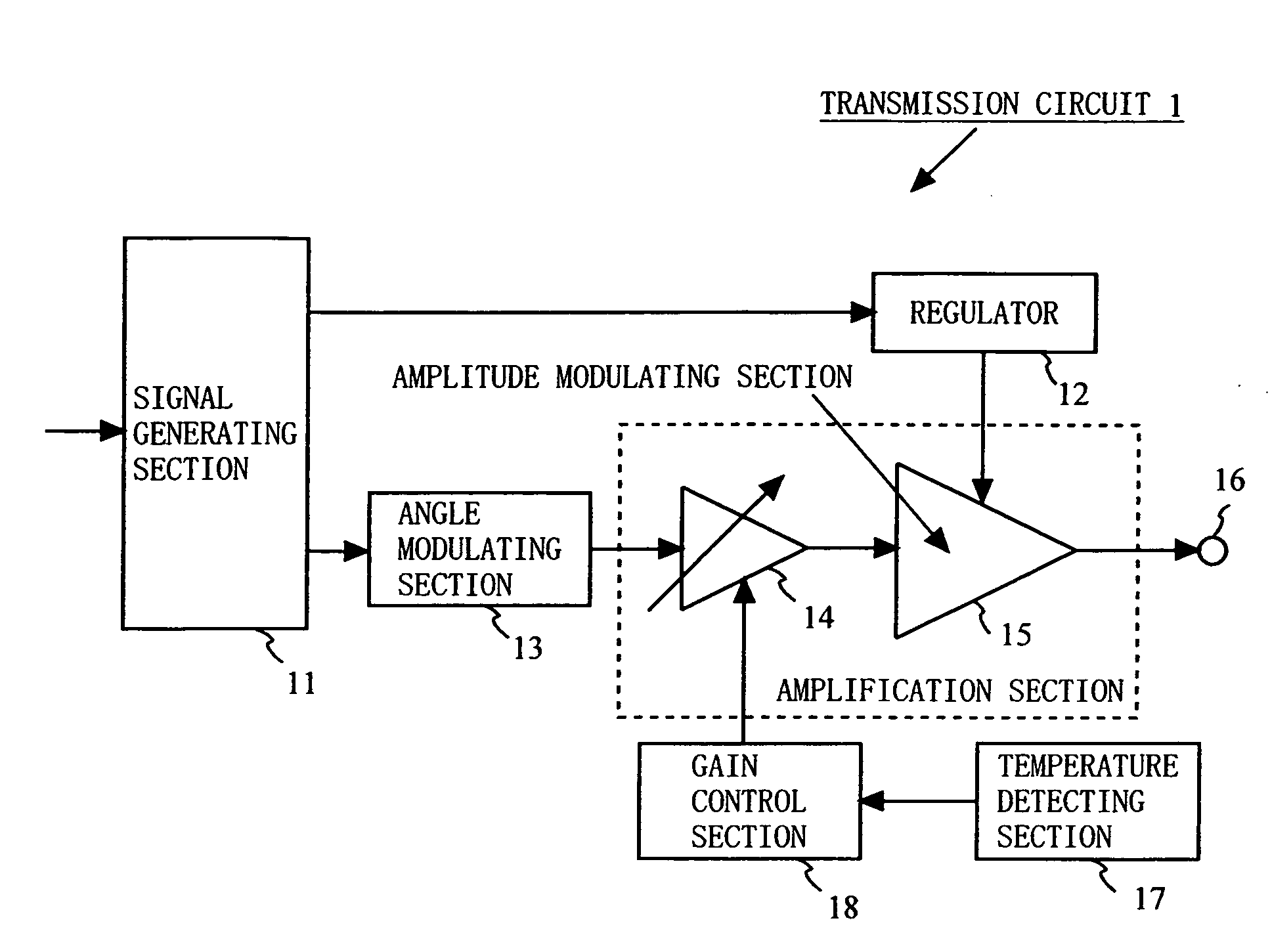
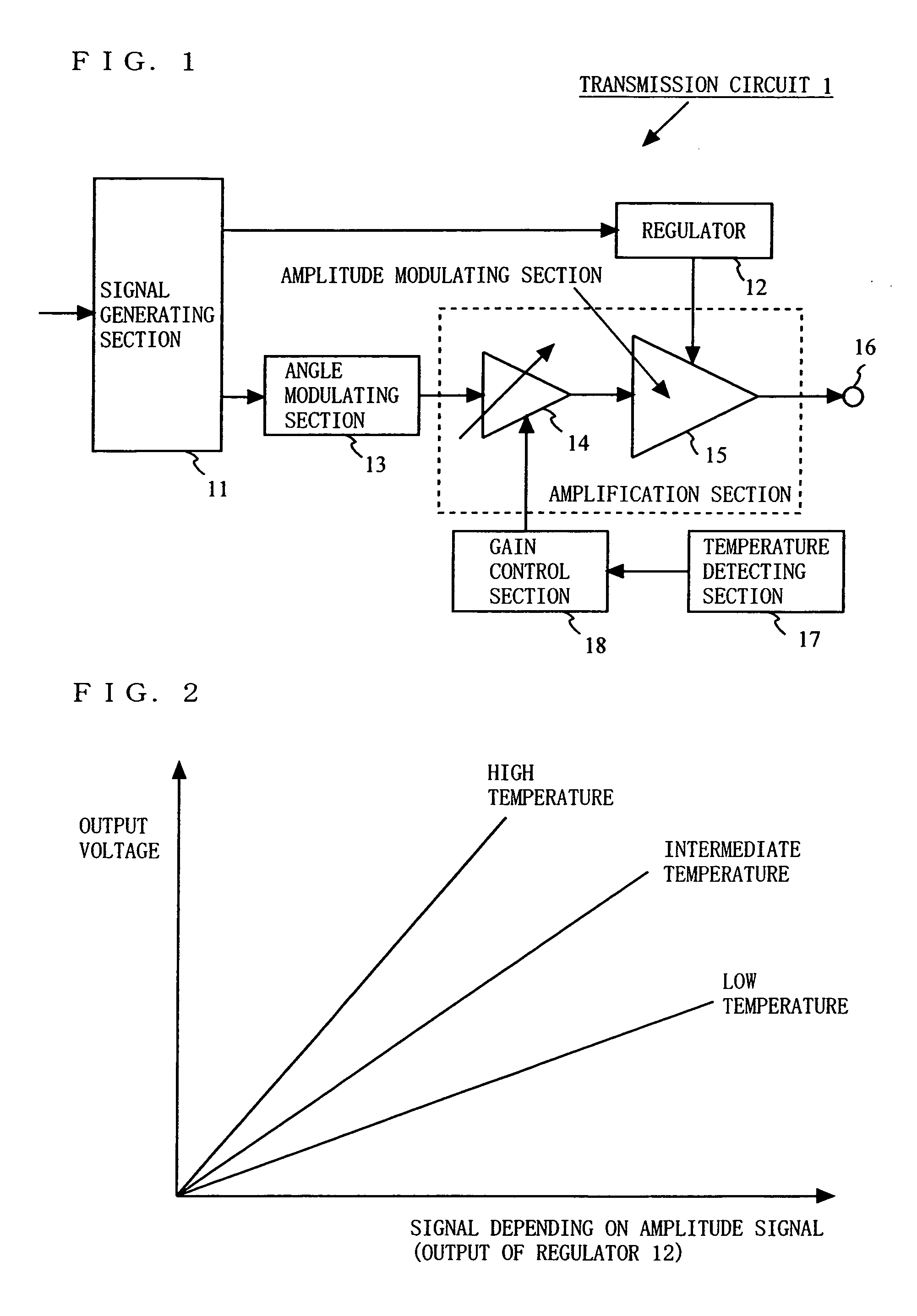
[0073]FIG. 1 is a block diagram illustrating an exemplary configuration of a transmission circuit 1 according to a first embodiment of the present invention. In FIG. 1, the transmission circuit 1 comprises a signal generating section 11, a regulator 12, an angle modulating section 13, a variable gain amplifier 14, an amplitude modulating section 15, an output terminal 16, a temperature detecting section 17, and a gain control section 18. Note that the variable gain amplifier 14 and the amplitude modulating section 15 may be simply described as an amplification section.

[0074] The signal generating section 11 generates an amplitude signal and a phase signal, depending on input data. For example, the signal generating section 11 generates an amplitude signal and a phase signal based on an amplitude component and a phase component obtained by subjecting the input data to signal processing. Note that the signal generating section 11 may be referred to as a polar-coordinate signal genera...

second embodiment

[0095]FIG. 11 is a block diagram illustrating an exemplary configuration of a transmission circuit 2 according to a second embodiment of the present invention. In FIG. 11, the transmission circuit 2 comprises a signal generating section 11, a regulator 12, an angle modulating section 13, an amplitude modulating section 15, an output terminal 16, a temperature detecting section 17, and a gain control section 18a. Note that the amplitude modulating section 15 may be simply referred to as an amplification section.

[0096] The signal generating section 11 generates an amplitude signal and a phase signal based on input data. The amplitude signal generated in the signal generating section 11 is input to the regulator 12. The regulator 12 outputs a signal depending on a magnitude of the input amplitude signal. Typically, the regulator 12 outputs a signal having a magnitude which is proportional to the magnitude of the amplitude signal. The signal output from the regulator 12 is input to the...

third embodiment

[0105]FIG. 15 is a block diagram illustrating an exemplary configuration of a transmission circuit 3 according to a third embodiment of the present invention. In FIG. 15, the transmission circuit 3 is the same as the transmission circuit 1 of the first embodiment, except that the transmission circuit 3 further comprises an offset control section 19 and an offset compensating section 20. The offset control section 19 outputs an AM offset value which is to be added to an amplitude signal, based on the temperature information output from the temperature detecting section 17. The offset compensating section 20 adds the AM offset value output from the offset control section 19 to the amplitude signal.

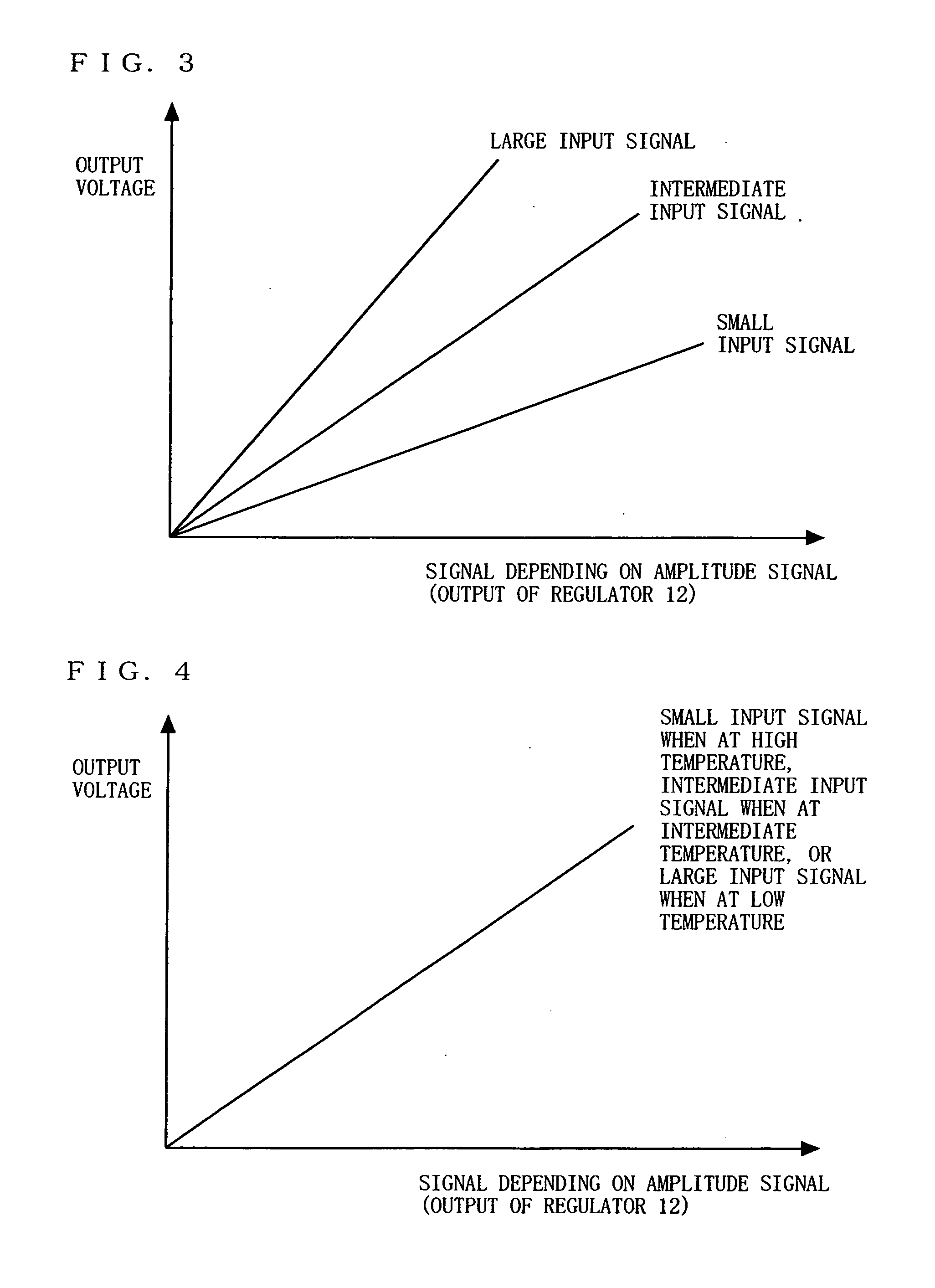
[0106]FIG. 16 is a diagram illustrating an example of the characteristics of the amplitude modulating section 15. When the amplitude modulating section 15 includes, for example, a Heterojunction Bipolar Transistor (HBT), the amplitude modulating section 15 exhibits characteristics as illust...


PUM


Abstract

A transmission circuit is provided which can output a stable transmission signal independently of the temperature characteristics of an amplitude modulating section. A signal generating section generates an amplitude signal and a phase signal. A regulator supplies a voltage which is controlled, depending on the amplitude signal, to the amplitude modulating section. An angle modulating section subjects the phase signal to angle modulation to output an angle-modulated signal. A temperature detecting section outputs temperature information of the amplitude modulating section. A gain control section controls a gain of a variable gain amplifier based on the temperature information of the amplitude modulating section. The variable gain amplifier amplifies the angle-modulated signal using the gain controlled by the gain control section. The amplitude modulating section subjects the angle-modulated signal to amplitude modulation using a voltage which is controlled, depending on the amplitude signal, to output an amplitude-modulated signal.

Description

BACKGROUND OF THE INVENTION [0001] 1. Field of the Invention [0002] The present invention relates to a transmission circuit for use in a communication apparatus for mobile telephony, wireless LAN, or the like. More particularly, the present invention relates to a transmission circuit which outputs a transmission signal having high linearity independently of the bandwidth and operates with high efficiency, and a communication apparatus employing the transmission circuit. [0003] 2. Description of the Background Art [0004] There is a demand for a communication apparatus for mobile telephony, wireless LAN, or the like which can secure the linearity of an output signal and operate with low power consumption even when it operates within a broad bandwidth. In such a communication apparatus, a transmission circuit is employed which outputs a transmission signal having high linearity independently of the bandwidth and operates with high efficiency. Hereinafter, conventional transmission circ...

Claims


Application Information

Patent Timeline
IPC IPC(8): H04B1/02H04B1/04H01Q11/12
CPCH04L27/361H04L27/366
Inventor MATSUURA, TORUMORIMOTO, SHIGERU
Owner INTEL CORP
Why Eureka
Try Eureka