Out-of-band remote management station

a remote management station and out-of-band technology, applied in the field of out-of-band remote management stations, to achieve the effect of improving the security of authenticating

Inactive Publication Date: 2007-06-07
INFINITE BAY TELECOM LIABILITY +1
View PDF99 Cites 73 Cited by
  • Summary
  • Abstract
  • Description
  • Claims
  • Application Information

AI Technical Summary

Benefits of technology

[0044] The existence of a network connection to the primary data network also allows the RMS to implement client protocols for centralized Authentication, Authorization, Accounting, and Auditing (AAAA) the same as many other networked devices do. An example of such a protocol would be RADIUS. This would allow the RMS to do strong authentication and authorization by connecting to a centralized server like Cisco's Access Control Server and eliminate a security hole. FIG. 4 illustrates an ACS in the network for the RMS to access.
[0051] The secure mode of operation of the RMS allows information that would otherwise be transmitted in clear text between the user and the router to be encrypted by the RMS and be protected between the RMS and the user. The information would only be in clear text between the router console port and the RMS and both these devices should be physically secured together. Since some of this information could be router configurations and passwords, protecting this information is vital.
[0055] The RMS can also be configured to execute a macro before a call is connected to a serial port or when a call is disconnected from a serial port. In the case of the serial port being connected to a Cisco console a major advantage of this would be or automatically have the RMS log out a user from the console as soon as a call becomes disconnected and not allow any new called to connect to that port until the previous user has been disconnected. This can be used to force each user to log in with their own userid without any risk of them inheriting the previous users privileges without logging in.
[0056] The connections from the RMS to the data network(s) allow users to connect to the RMS and gain access to the DTE connections from the RMS using the primary data network as shown in FIG. 19 in addition to the connection to the RMS via the PSTN network. This call reduce long distance charges and provide for a faster connection when the primary data network connection(s) are up. In addition, the user has the option of connecting to the RMS in secure mode over the network, protecting the information from the user to the RMS and then connecting from the RMS to the console port of the router over the serial interface. As shown in FIG. 20 the RMS could also be configured to allow the user to connect to the RMS in secure mode and then connect to the router over a network connection using Telnet. This would still protect the information from the user to the RMS and only expose the information as clear text from the RMS to the router. If the connection from the RMS to the router were a physically secure back-to-back Ethernet connection, the exposure of the information would virtually be eliminated. This would be useful where it is impractical to implement an Internet Protocol Security (IPSec) connection to the router for management or where the router software does not yet support IPSec or Secure shell.
[0060] The RMS can also provide a means of “cycling” the power for another device such as a router. Allowing an administrator to power cycle a router and connect to the console port could save needing to send a technician to a remote site for certain operations such as password recovery. While logged into the RMS the remote technician can cause the router to be power cycled and then connect to the console port to perform password recover.
[0062] Another method of protecting against a denial-of-service attack on the PSTN line is for the RMS to be able to securely connect to an application that works with the PSTN local loop provider to manage call blocking. This is depicted in FIG. 27. This application would allow a subscriber to dynamically change a list of numbers to allow or block calls from as well as change if calls without the calling number being available will be accepted. This application would allow PSTN numbers originating attacks to be blocked in the provider network leaving the local loop to the RMS available for calls from authorized users.

Problems solved by technology

However, the lack of an exemplary embodiment for a particular application of the inventive feature does not imply that the application is not protected by the claims.

Method used


Image

  • Out-of-band remote management station
  • Out-of-band remote management station
  • Out-of-band remote management station

Examples


Embodiment Construction

[0094] The present invention now will be described more fully hereinafter with reference to the accompanying drawings, in which preferred embodiments of the invention ale shown. This invention may, however; be embodied in many different forms and should not be construed as limited to the embodiments set forth herein; rather, these embodiments are provided so that this disclosure will be thorough and complete, and will fully convey the scope of the invention to those skilled in the art. Like numbers refer to like elements throughout.

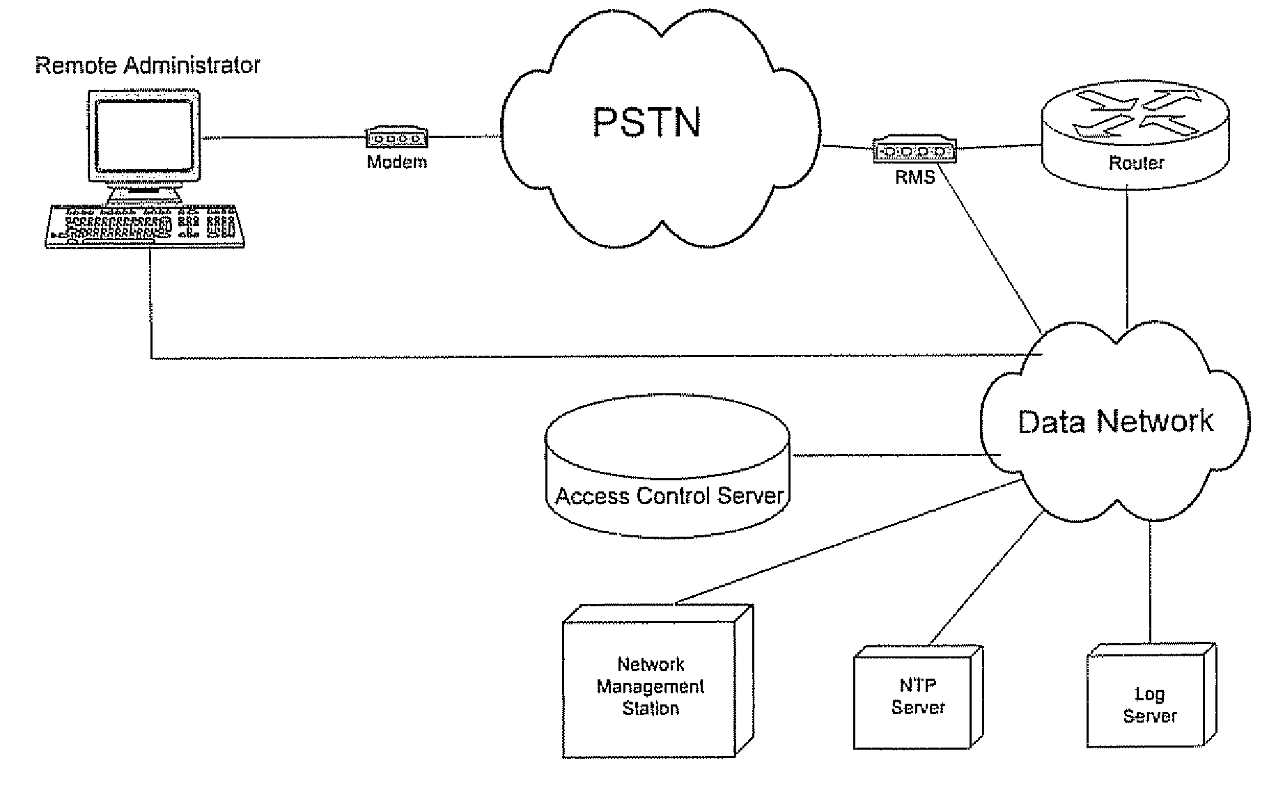
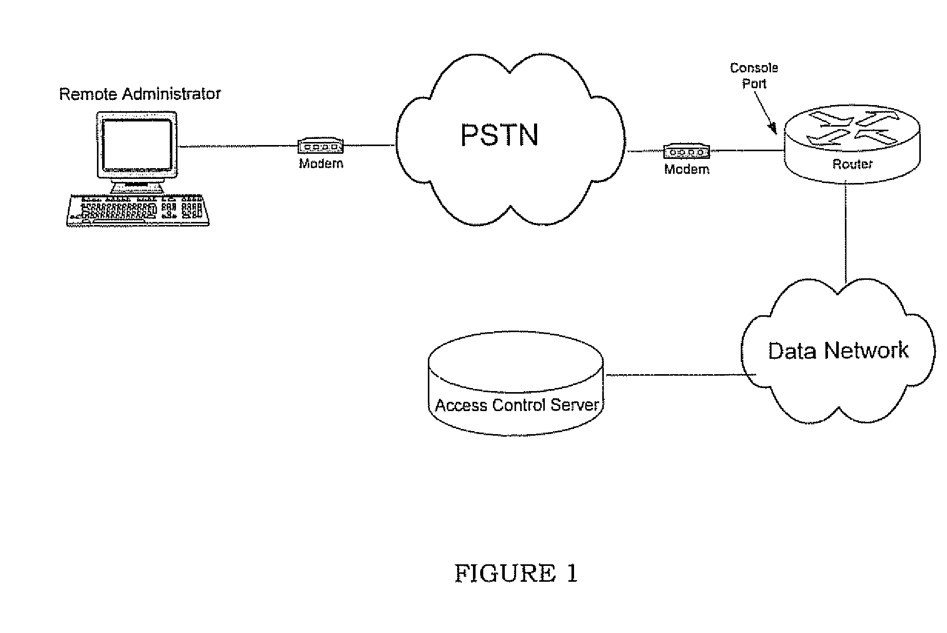
[0095] The preferred exemplary embodiment of the Remote Management Station (RMS) of the present invention, as illustrated in FIGS. 5 through 7, comprises a management station to assist a remote network administrator in securely managing a networking device such as a router or switch in an environment such as that depicted in FIG. 4. The RMS provides the remote operator with a number of capabilities that will be looked at individually. Having an embedded ...


PUM


Abstract

A management system for a computer data network comprises a remote management station connected to an analog communication system and connected to a device console port of a co-located computer device. The remote management station comprises (a) an embedded processor, (b) a connecting means to the analog communication system, and (c) a connecting means to the device console port. The remote management station is configured to detect a user connecting to or disconnecting from the device console port via the remote management station. The remote management station is configured for one or more of the following: (a) logging the user off the device console port when the user disconnects or is disconnected from the console port; (b) logging a previous user off the device console port before allowing a new user to access the device console port; or (c) monitoring messages sent to the device console port.

Description

CROSS-REFERENCE TO RELATED APPLICATIONS [0001] This application is a continuation of U.S. application Ser. No. 10 / 461,820, filed Jun. 13, 2003, which in turn claims priority to U.S. Provisional Application No. 60 / 388,287, filed Jun. 13, 2002 and U.S. Provisional Application No. 60 / 438,282, filed Jan. 6, 2003, the contents of which are incorporated herein by reference in its entirety. The present invention is related to the invention described in co-owned, co-pending patent application Ser. No. 10 / 461,827, filed on Jun. 13, 2003, the contents of which are incorporated herein by reference in its entiretyFIELD OF THE INVENTION [0002] The present invention relates in general to methods and apparatus used in communications over a telephony network and more particularly to methods and apparatus for secure communications of remote management and monitoring of network elements and reporting the status of the elements. BACKGROUND OF THE INVENTION [0003] In computer networks with remote netwo...

Claims


Application Information

Patent Timeline
Patent Type & Authority Applications(United States)
IPC IPC(8): G06F15/173H04L9/00H04L12/10H04L12/24H04L12/26H04L29/06H04M3/22
CPCH04L12/10H04L12/2602H04L41/0246H04L41/06H04L41/0803H04L41/082H04L41/28H04L43/00H04L43/065H04L43/0811H04L43/0817H04L43/106H04L63/0227H04L63/104H04L63/1441H04L63/18H04M3/2263H04M3/303H04L63/168H04L63/08H04L41/344
Inventor CARLEY, JEFFREY A.
Owner INFINITE BAY TELECOM LIABILITY
Why Eureka
Try Eureka