Self-synchronizing hardware/software interface for multimedia SOC design

Inactive Publication Date: 2007-06-07
MOBILIC TECH CAYMAN CORP
View PDF8 Cites 2 Cited by
  • Summary
  • Abstract
  • Description
  • Claims
  • Application Information

AI Technical Summary

Benefits of technology

[0019] It is an object of at least one embodiment of the present invention to provide a method of synchronizing the exchange of data between hardware and software,

Problems solved by technology

The above scheme often results in frequent and inefficient HW/SW communications.
As a result, it may not be able to respond to the HW interrupt in time.
Precious HW clock cycles are thus wasted on waiting for further instructions from the CPU.
The HW/SW synchronization becomes an even more important issue when HW an

Method used


Image

  • Self-synchronizing hardware/software interface for multimedia SOC design
  • Self-synchronizing hardware/software interface for multimedia SOC design
  • Self-synchronizing hardware/software interface for multimedia SOC design

Examples


Embodiment Construction

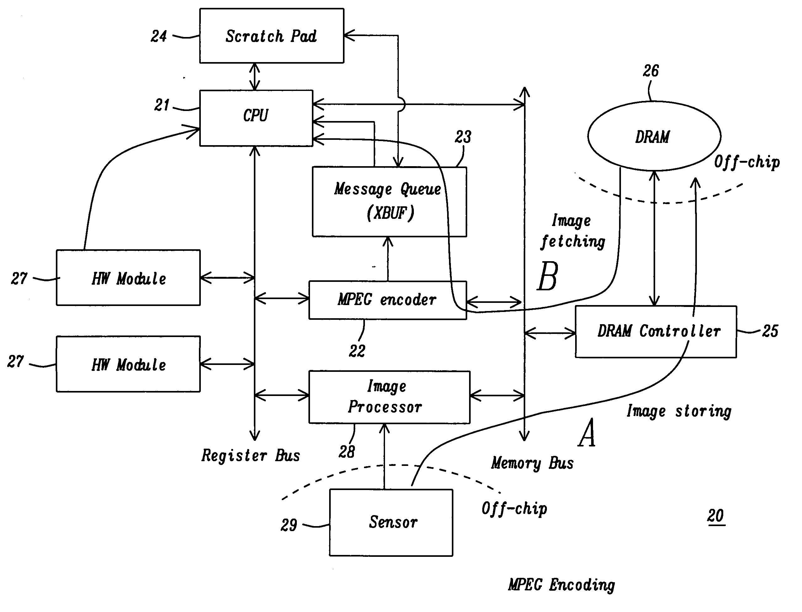
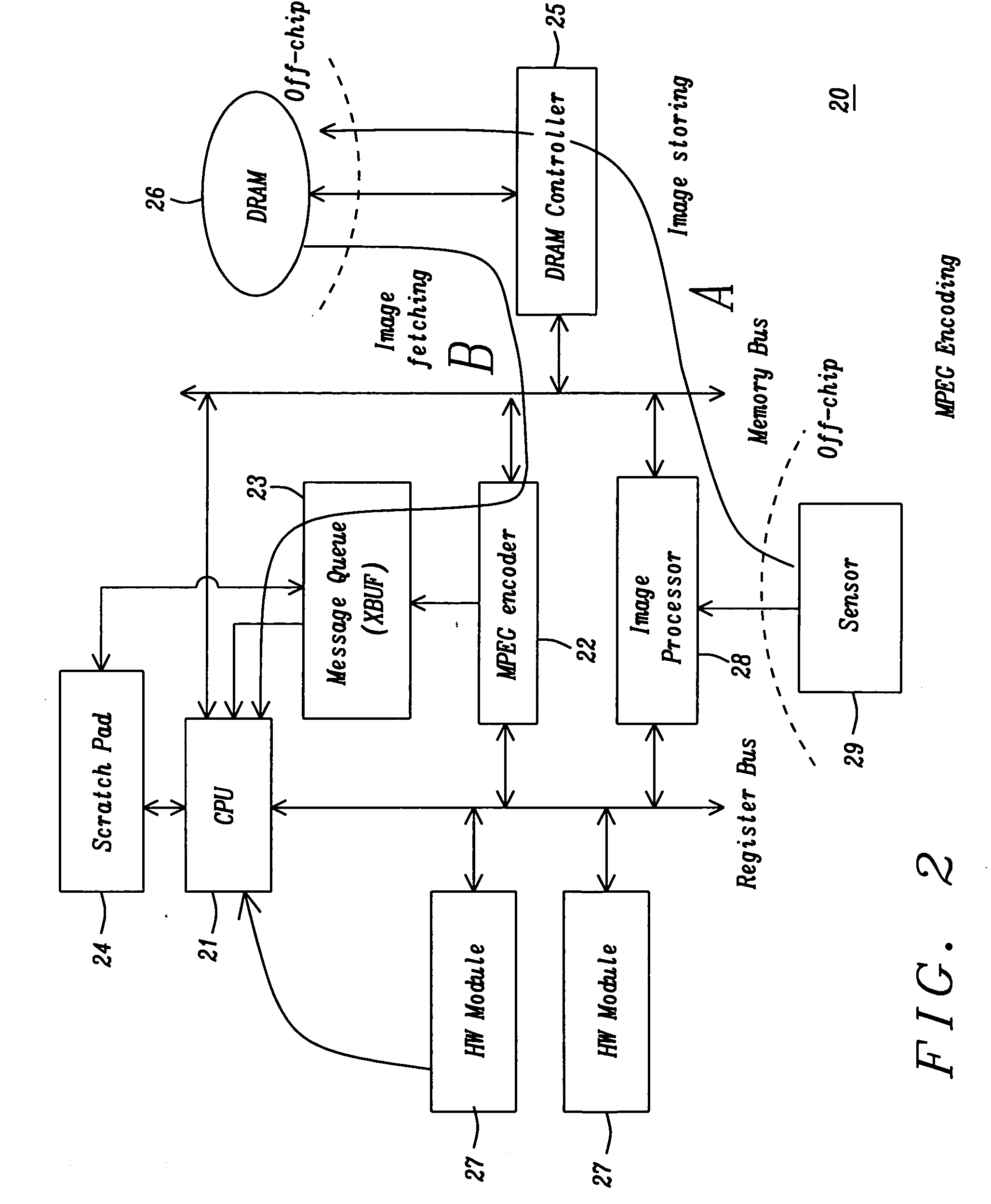
[0029] The present invention provides a very successful solution of the problem outlined above by using a combined data / control message queue between the hardware (HW) and the software (SW) as a solution to the HW / SW synchronization problem. We call this combined data / control message queue the XBUF (Xfer buffer). Our application is MPEG encoding and decoding, but the invention itself is general in nature and can easily be extended to other SOC applications such as communications, data storage, etc. Whenever data processing is shared by HW and SW, the present inventive technique can apply. The queue depth of the XBUF can be either fixed or variable, depending on the application requirement. The larger the potential speed difference between the HW and the SW is, the deeper the queue needs to be. The message words in the XBUF are tagged to indicate whether a particular word contains data or control information (essentially MPEG control information). Different tags correspond to differe...


PUM


Abstract

A forced lock-step operation between a CPU (software) and the hardware is eliminated by unburdening the CPU from monitoring the hardware until it is finished with its task. This is done by providing a data/control message queue into which the CPU writes combined data/control messages and places an End tag into the queue when finished. The hardware checks the content of the message queue and starts decoding the incoming data. The hardware processes the data read from the message queue and the processed data is then written back into the message queue for use by the software. The hardware raises an interrupt signal to the CPU when reaching the End tag. Speed differences between hardware and software can be compensated for by changing the depth of the queue.

Description

BACKGROUND OF THE INVENTION [0001] 1. Field of the Invention [0002] The invention relates to a method of synchronizing the exchange of data between hardware and software via a buffer containing both data and control information, and more particularly where the CPU is not required to synchronize the data exchange between hardware and software thereby saving clock cycles. [0003] 2. Description of the Related Art [0004] Typically, the hardware (HW) in a System-On-Chip (SOC) design operates in the following fashion, as shown in FIG. 1, a flowchart of the prior art. [0005] 1. Block 10: the hardware stays in the idle state, waiting for instructions from the software (SW, i.e. CPU). [0006] 2. Block 11: the CPU programs the registers in the hardware module to set up various control information. [0007] 3. Block 12: after register programming is finished, the CPU enables the hardware (Block 13). [0008] 4. Block 14: the hardware starts performing the desired operations as specified by the cont...

Claims


Application Information

Patent Timeline
IPC IPC(8): G06F5/00
CPCG06F13/4234G06F2213/0038H04N21/443
Inventor WANG, LINCHENGTSAI, CHING-HANCHANG, CHENG-LUNDURVASULA, UMA SHANKARREN, JAU-WEN
Owner MOBILIC TECH CAYMAN CORP
Why Eureka
Try Eureka