Exhaust heat augmentation in a combined cycle power plant

Inactive Publication Date: 2007-06-14
SIEMENS ENERGY INC
View PDF54 Cites 115 Cited by
  • Summary
  • Abstract
  • Description
  • Claims
  • Application Information

AI Technical Summary

Problems solved by technology

However, it is expensive to purchase and maintain basic plant capacity for peak loads.
Thus, these firings are inefficient by comparison to combustion in the gas turbine combustor.
However, they can provide a large immediate increase of heat to the HRSG.
Tradeoffs are costs of base capacity versus costs of less efficient supplemented operation during peak loads.
However, if fuel costs and/or power demand rises faster than predicted, a pl

Method used


Image

  • Exhaust heat augmentation in a combined cycle power plant
  • Exhaust heat augmentation in a combined cycle power plant
  • Exhaust heat augmentation in a combined cycle power plant

Examples


Embodiment Construction

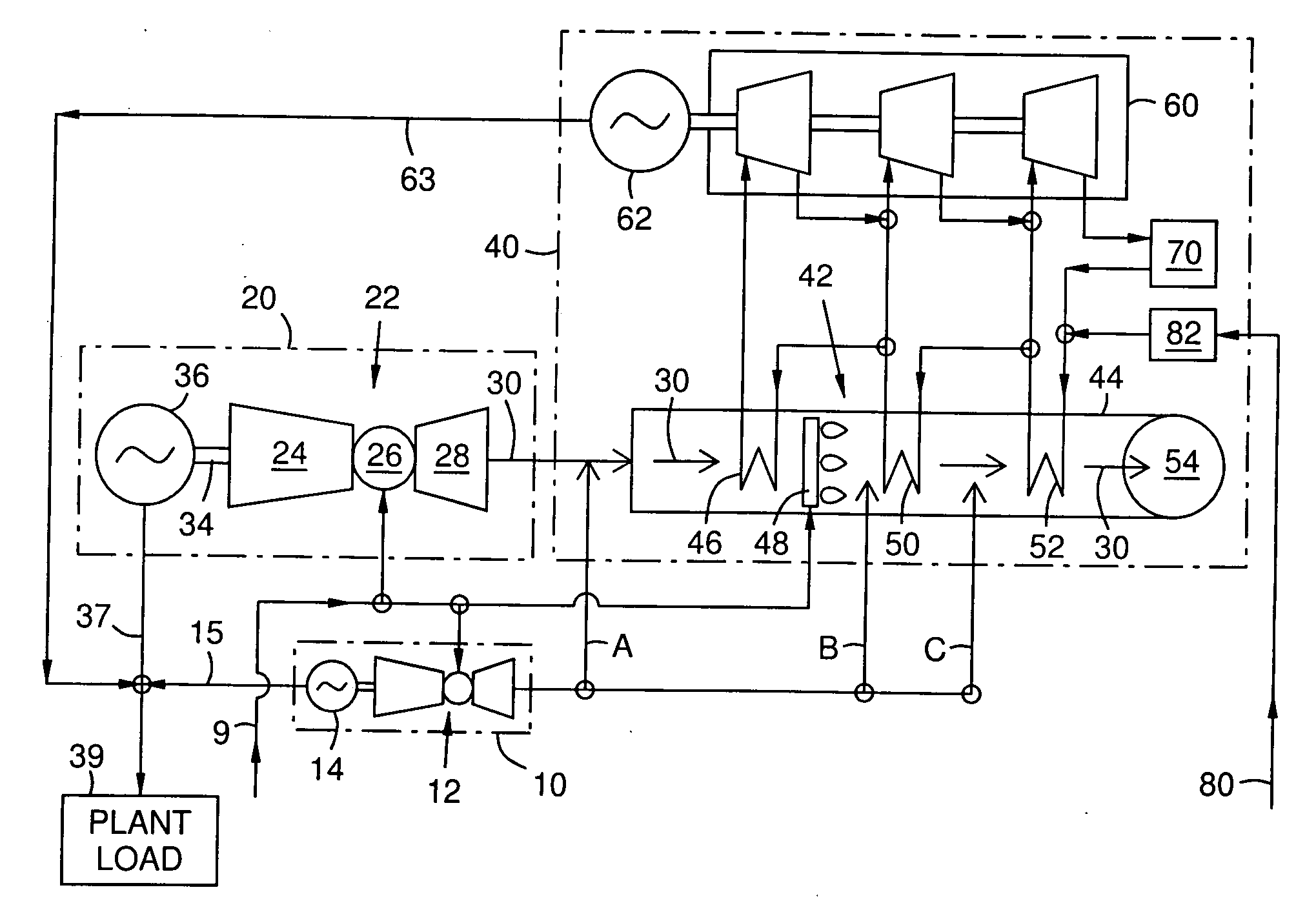
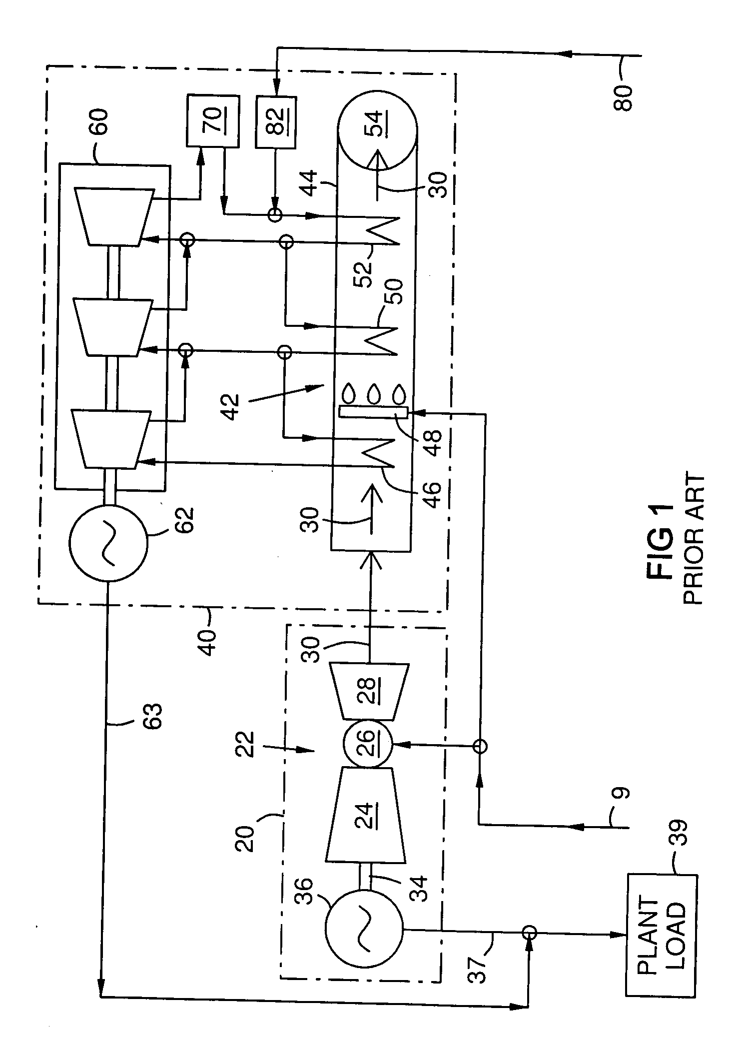
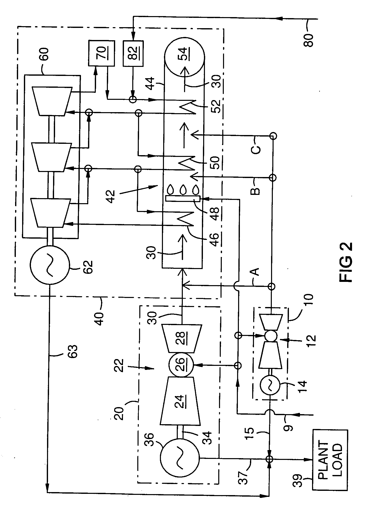
[0014]FIG. 1 is a schematic diagram of a prior art combined cycle power plant comprising a base topping cycle 20, and a base bottoming cycle 40. The topping cycle comprises a base gas turbine engine 22 with a compression section 24, a combustion section 26, a turbine section 28, an exhaust flow 30, and a power output shaft 34 that drives a generator 36 for electrical output 37. A fuel flow 9 is provided to the combustion section 26. The bottoming cycle 40 comprises a heat recovery steam generator (HRSG) 42 with a gas duct 44 and one or more heat exchangers 46, 50, 52 that transfer heat from the exhaust flow 30 to water 70, 80 to generate steam for powering steam turbines 60 and / or for cogeneration uses such as factory heating or manufacturing (not illustrated). A given heat exchange loop 46, 50, 52 may include several elements, such as preheater, drum, evaporator, and superheater, as known in the art. These elements heat incoming water pumped 82 from an external water source 80 and / ...


PUM


Abstract

A method and system for augmenting the output of a combined cycle power plant having a base gas turbine (22) driving a generator (36) and a heat recovery steam generator (42) that recovers exhaust heat (30) from the base gas turbine (22) to drive a steam turbine (60). A complementary gas turbine engine (12) is added to the power plant to drive a complementary generator (14). The exhaust (A, B, C) of the complementary gas turbine (12) is merged into the flow path of exhaust gas (30) from the base gas turbine (22) upstream of a selected one or more heat exchangers (46, 50, 52) in the heat recovery steam generator (42). Such a complementary system (10) may be used together with supplemental duct burners (48) in a hybrid augmentation embodiment.

Description

FIELD OF THE INVENTION [0001] This invention relates generally to the field of combined cycle power plants. BACKGROUND OF THE INVENTION [0002] A “topping cycle” generates electricity and / or mechanical energy first, and produces waste heat secondarily as a byproduct. A “bottoming cycle” recovers waste heat from a topping cycle to generate electricity and / or mechanical energy. Combined cycle power plants combine a topping cycle and a bottoming cycle to maximize fuel efficiency. Combined cycle power plants are known as efficient means for converting fossil fuels to electrical energy. These plants may have both a gas turbine (GT) and a steam turbine (ST) driving electrical generators. Exhaust heat from the gas turbine is recovered by a heat recovery steam generator to drive the steam turbine. [0003] A heat recovery steam generator (HRSG) is a heat exchange device that uses the hot exhaust from a topping cycle such as a gas turbine to generate steam. This steam is used to generate electr...

Claims


Application Information

Patent Timeline
IPC IPC(8): F02C6/18
CPCF02C6/02F02C6/18Y02E20/14Y02E20/16F05D2240/40
Inventor COPEN, JOHN H.
Owner SIEMENS ENERGY INC
Why Eureka
Try Eureka