
Local cooling hole pattern

a gas turbine engine and local cooling technology, applied in the direction of hot gas positive displacement engine plants, combustion processes, lighting and heating apparatus, etc., can solve the problems of degrading the effectiveness, integrity and life of the liner, affecting the efficiency of the liner, so as to increase the cooling film effectiveness, improve the cooling airflow, and increase the amount of cooling airflow

Active Publication Date: 2007-06-14
RAYTHEON TECH CORP
View PDF15 Cites 36 Cited by
  • Summary
  • Abstract
  • Description
  • Claims
  • Application Information

AI Technical Summary

Benefits of technology

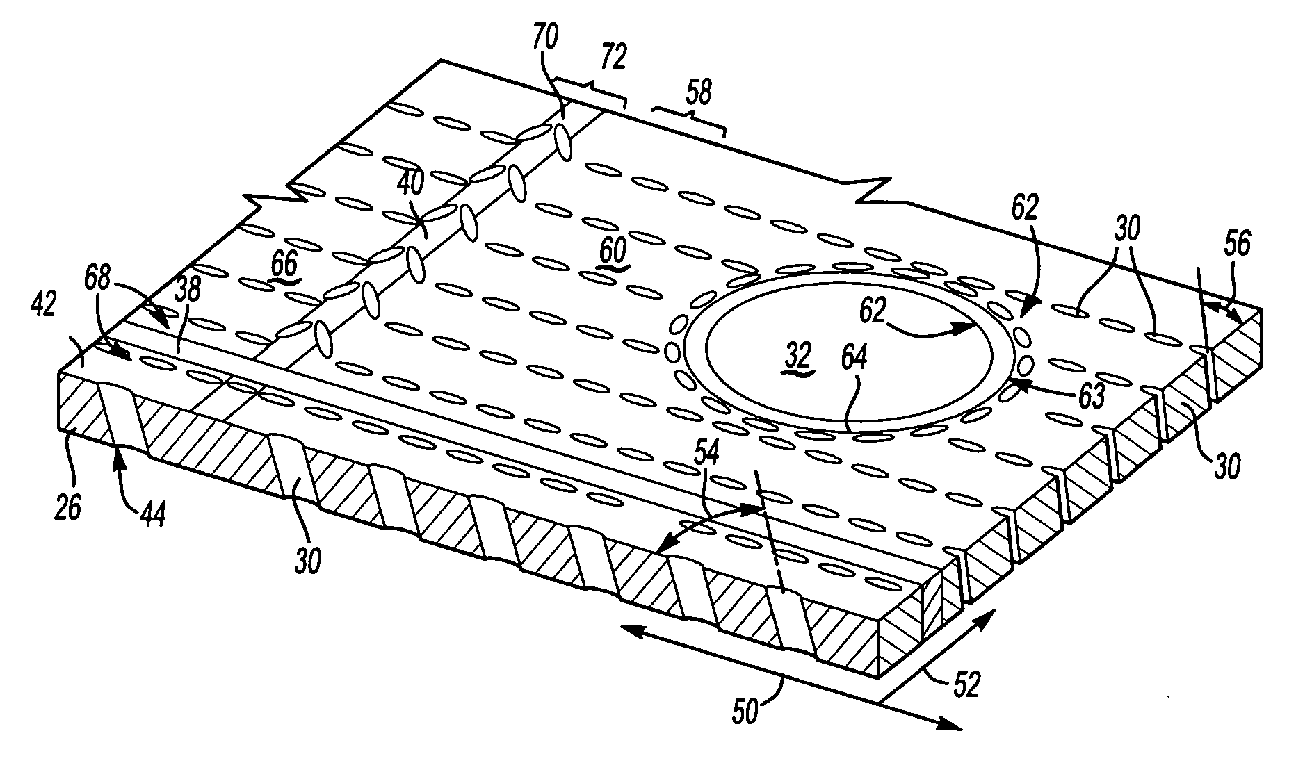
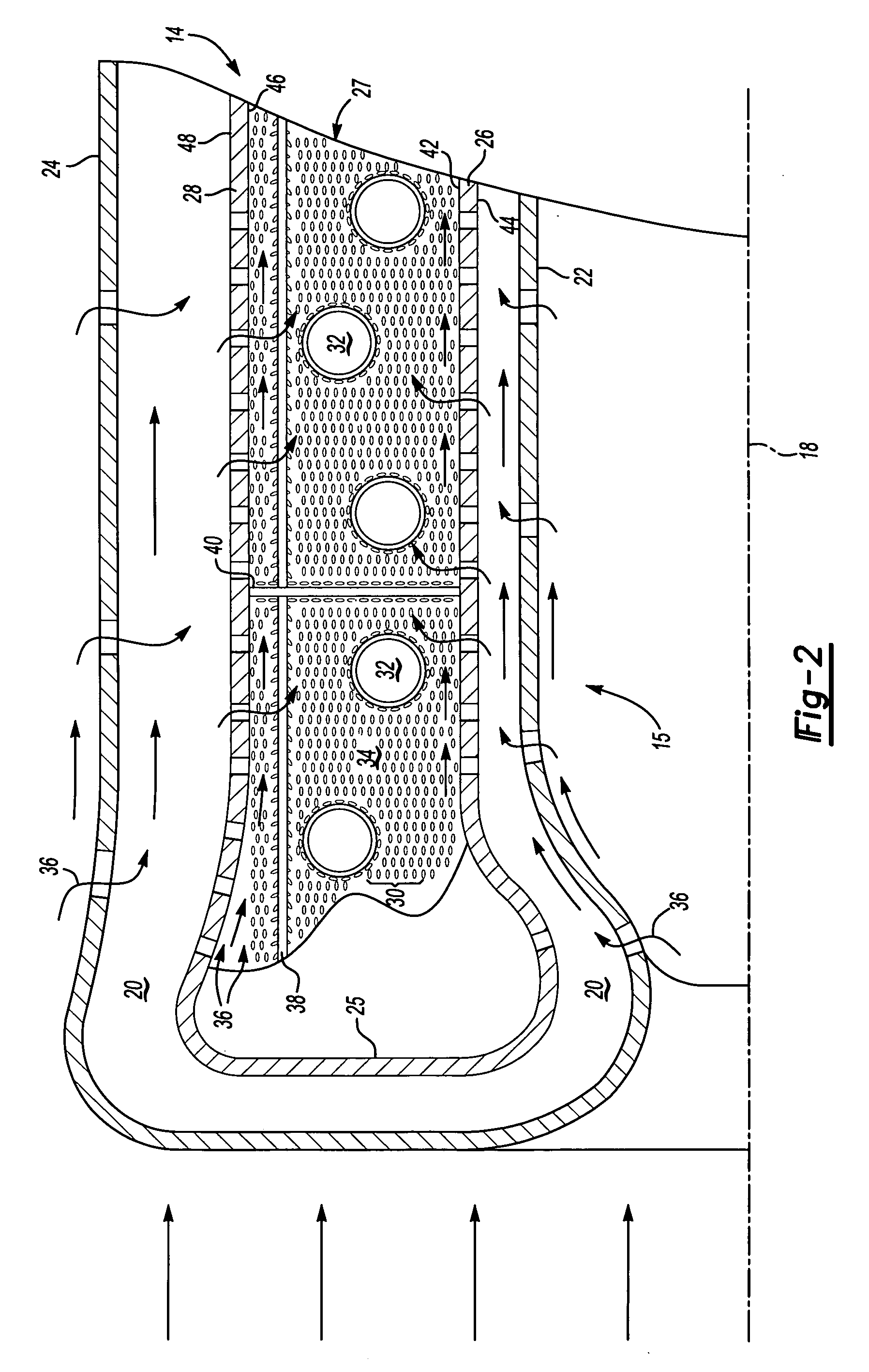
[0009] A second group of cooling holes is disposed adjacent to structural features that affect cooling airflow at a second compound angle relative to the structural features. The second group of cooling holes includes a second circumferential direction corresponding to the proximate structural feature. Each of the cooling holes in the second group also includes an inclination angle that is substantially the same as that of the first group of cooling holes. The second group of cooling holes surrounds the structural formations within the liner assembly to provide a non-uniform and structural feature specific arrangement of cooling holes to provide the cooling airflow that maintains desired wall temperatures and increases cooling film effectiveness without significantly increasing the amount of cooling airflow required.

Problems solved by technology

The thin layer of cooling air can be disrupted by flow around the larger openings potentially resulting in elevated liner temperatures adjacent the larger openings.
Further, the liner includes other structural features such as seams and rails that disrupt cooling airflow causing elevated temperatures.
Elevated or uneven temperature distributions within the liner can promote undesired oxidation of the liner material, coating-failure or thermally-induced stresses that degrade the effectiveness, integrity and life of the liner.
Disadvantageously, the greater cooling airflow provided around such openings and other disrupting configurations, utilizes a large portion of the limited quantity of cooling air provided to the combustor liner.
The increased demand for cooling airflow in the localized areas around larger opening and disruptions reduces the overall cooling airflow that is available for the remaining portions of the liner assembly.
The amount of cooling airflow is limited by the design of the combustor liner and increases in cooling airflow requirements can impact other design and performance requirements.

Method used


Image

  • Local cooling hole pattern
  • Local cooling hole pattern
  • Local cooling hole pattern

Examples


Embodiment Construction

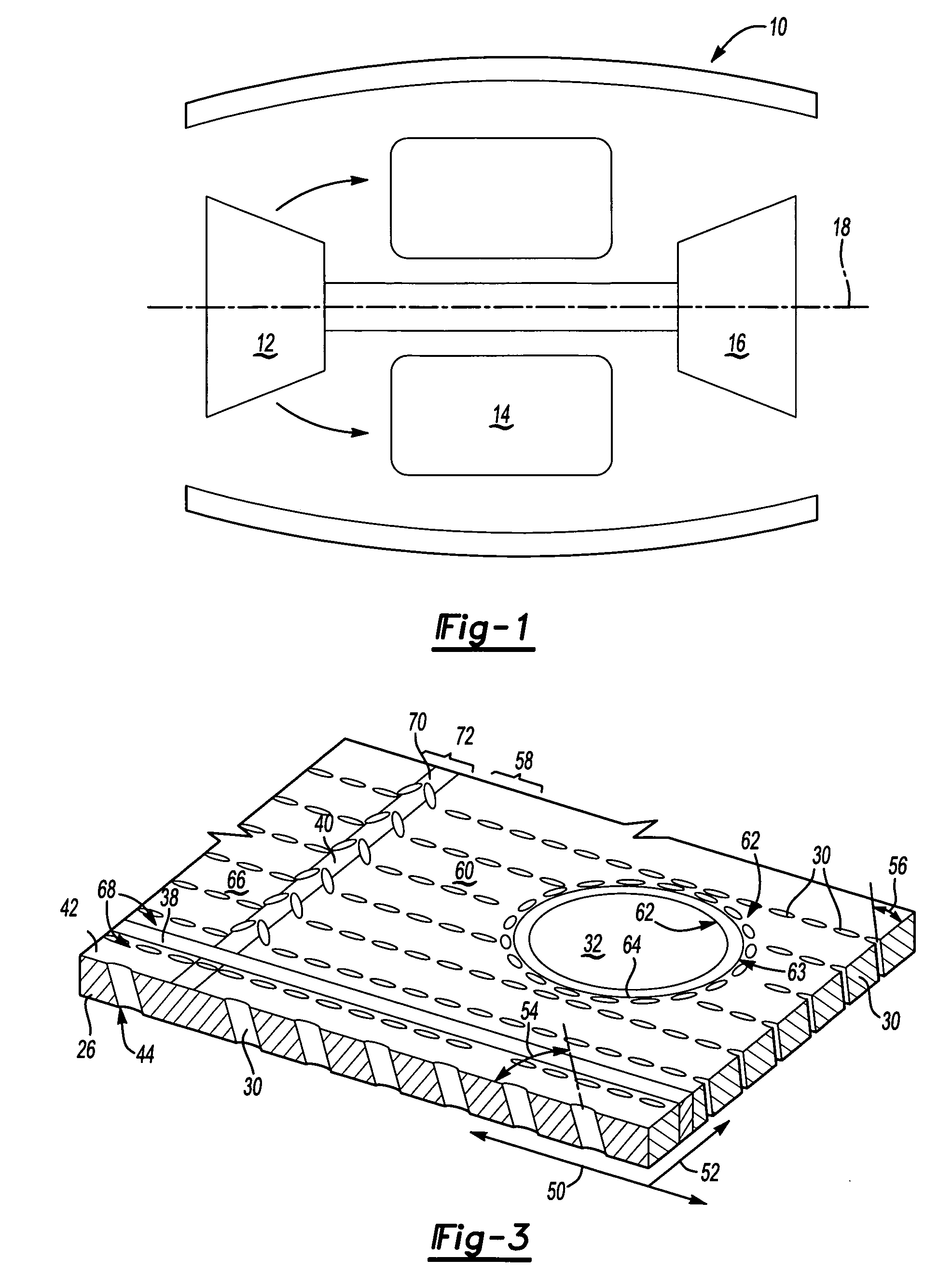
[0020] Referring to FIG. 1, a turbine engine assembly 10 includes a fan, a compressor 12 that feeds compressed air to a combustor 14. Compressed air is mixed with fuel and ignited within the combustor to produce hot gasses that are then driven past a turbine 16. The schematic representation of the turbine engine assembly 10 is intended for descriptive purposes, as other turbine engine assembly configurations will also benefit from the disclosures of this invention.

[0021] Referring to FIG. 2, the combustor assembly 14 includes a dual-wall liner assembly 15. The liner assembly 15 includes an inner shell 22 and an outer shell 24. The outer shell 24 and inner shell 22 are spaced radially apart from an inner heat shield 26 and an outer heat shield 28. The inner shell 22 and outer shell 24 are spaced a radial distance apart to define an air passage 20 between the outer heat shield 28 and the inner heat shield 26.

[0022] The example combustor assembly illustrated is disposed annularly abo...


PUM


Abstract

A combustor assembly includes an inner and an outer liner defining a combustion chamber. The inner and outer liner includes a plurality of cooling holes that are spaced a specified distance apart. The cooling holes include a specified inclination angle and circumferential angle. A first group of cooling holes is spaced apart according to a uniform geometric pattern and density. A second group disposed between the first group and some structural feature within the liner assembly is disposed at a non-uniform pattern and a hole density equal to the density of the first group of cooling holes. The non-uniform cooling hole arrangement increases cooling flow effectiveness to accommodate local disturbances and thermal properties.

Description

BACKGROUND OF THE INVENTION [0001] This invention relates generally to a combustor liner for a gas turbine engine. More particularly, this invention is a cooling hole configuration for providing a desired cooling airflow proximate to cooling airflow disrupting features of a combustor liner. [0002] Typically, a combustor module for a gas turbine engine includes an outer casing and an inner liner. The liner and the casing are radially spaced apart to form a passage for compressed air. The liner forms a combustion chamber within which compressed air mixes with fuel and is ignited. The liner includes a hot side exposed to hot combustion gases and a cold side facing the passage formed between the liner and the casing. Liners can be single-wall or double-wall construction, single-piece construction or segmented construction in the form of discrete heat shields, panels or tiles. [0003] Typically, a plurality of cooling holes supply a thin layer of cooling air that insulates the hot side of...

Claims


Application Information

Patent Timeline
IPC IPC(8): F23R3/06
CPCF23R3/06
Inventor BURD, STEVEN W.CHEUNG, ALBERT K.
Owner RAYTHEON TECH CORP
Learn More