Sealed container and manufacturing method thereof

a technology of sealing container and manufacturing method, which is applied in the direction of rigid containers, packaging, bottles, etc., can solve the problems of large use amount of metal material, large cost increase in the whole container, and difficulty in seaming process, so as to improve the recyclability of containers and improve the filling speed and transportation efficiency

Inactive Publication Date: 2007-06-14
KIRIN BREWERY CO LTD
View PDF7 Cites 21 Cited by
  • Summary
  • Abstract
  • Description
  • Claims
  • Application Information

AI Technical Summary

Benefits of technology

[0020] In the sealed container of the present invention, because the welded portion that was laser welded does not form a flange, there are no uneven shapes, the touch sensation of the mouth portion is good, and liquid dripping rarely occurs. This is achieved even without the use of polymer materials and excessive material of a flange portion which were required in metal cans. Further, the lid portion can be miniaturized. Furthermore, when the sealed container is a plastic container, because it does not require a screw-in type lid, the filling speed and tran...

Problems solved by technology

For this reason, a polymer material is required, and the use amount of metal material becomes large.
However, with regard to plastic beverage containers, it is difficult to carry out the seaming process, and plastic can con...

Method used


Image

  • Sealed container and manufacturing method thereof
  • Sealed container and manufacturing method thereof
  • Sealed container and manufacturing method thereof

Examples


first embodiment

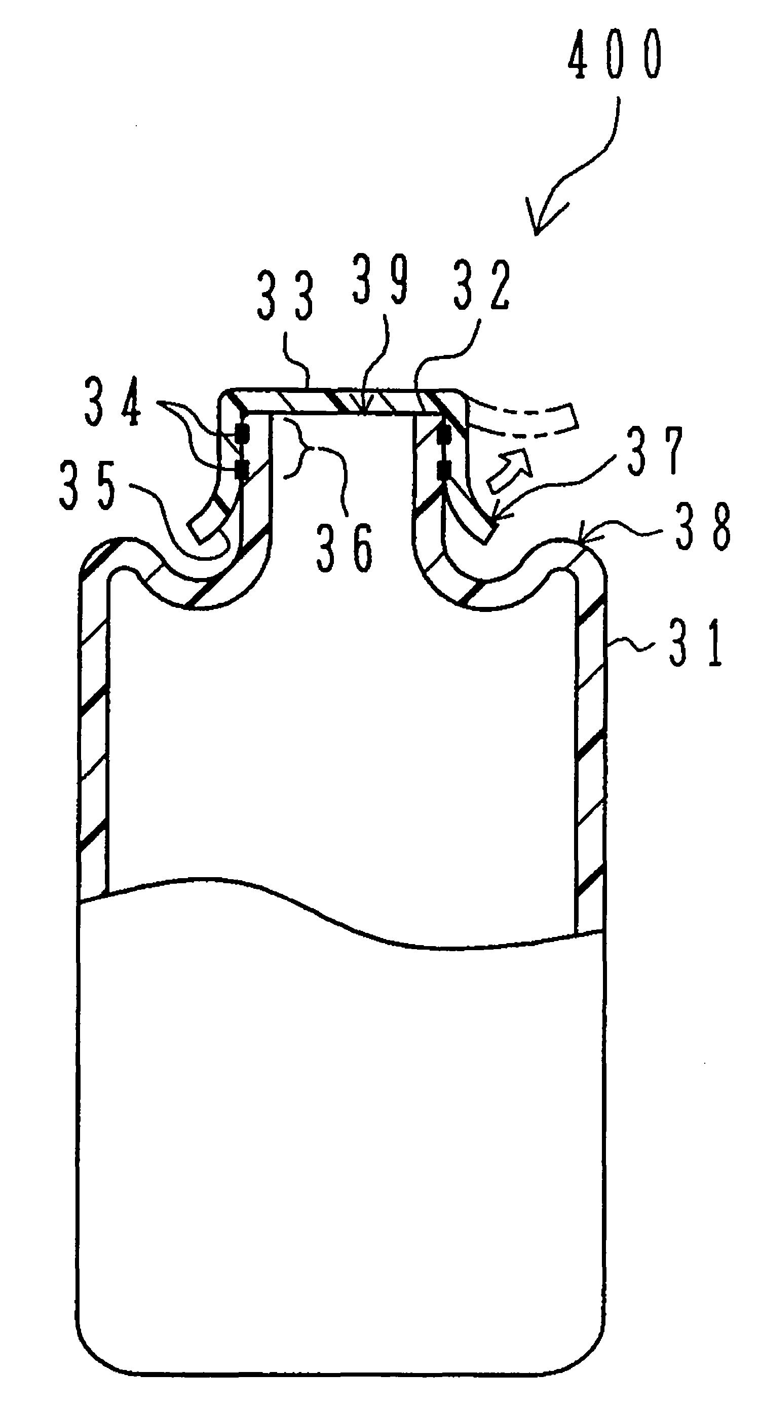
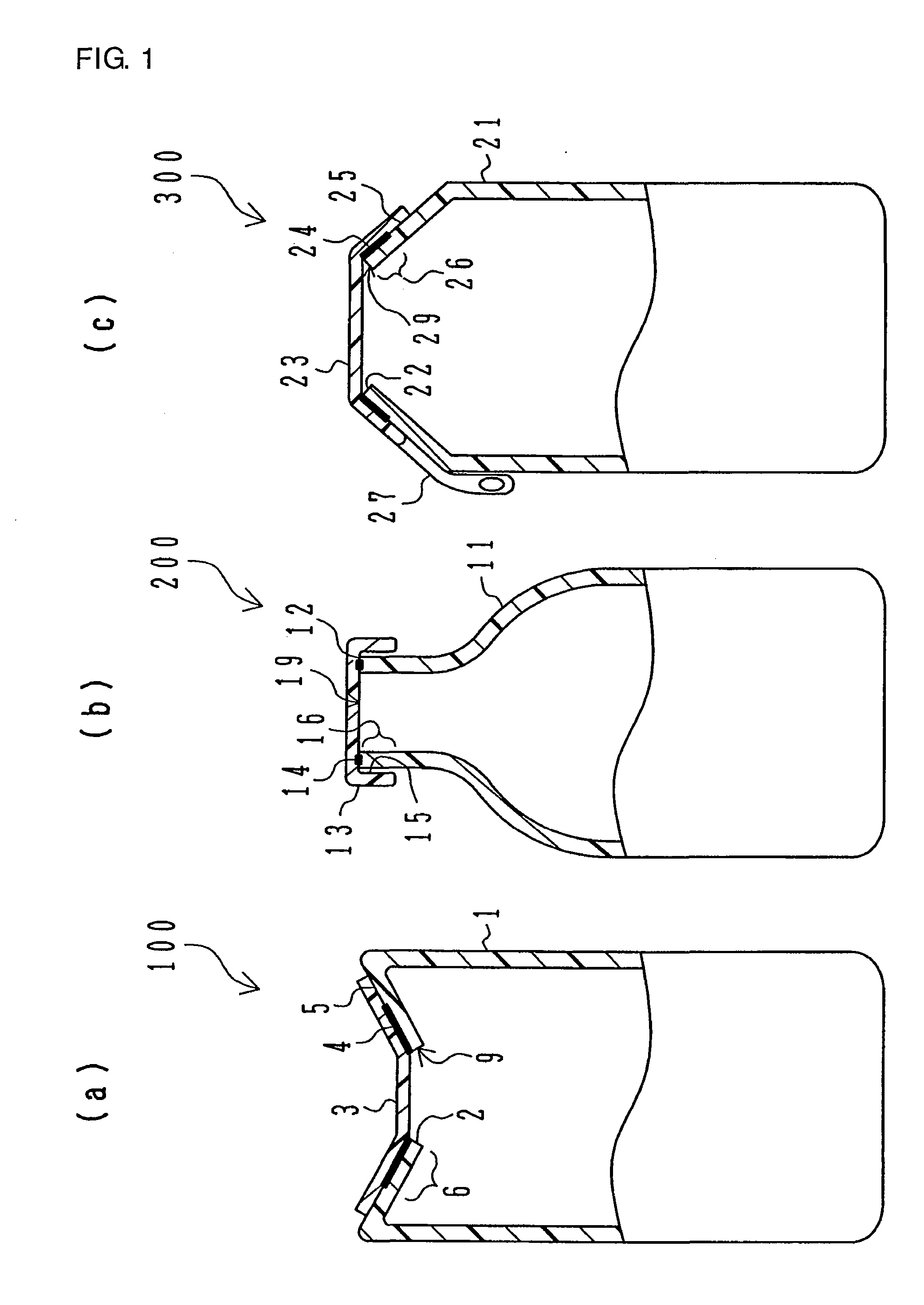
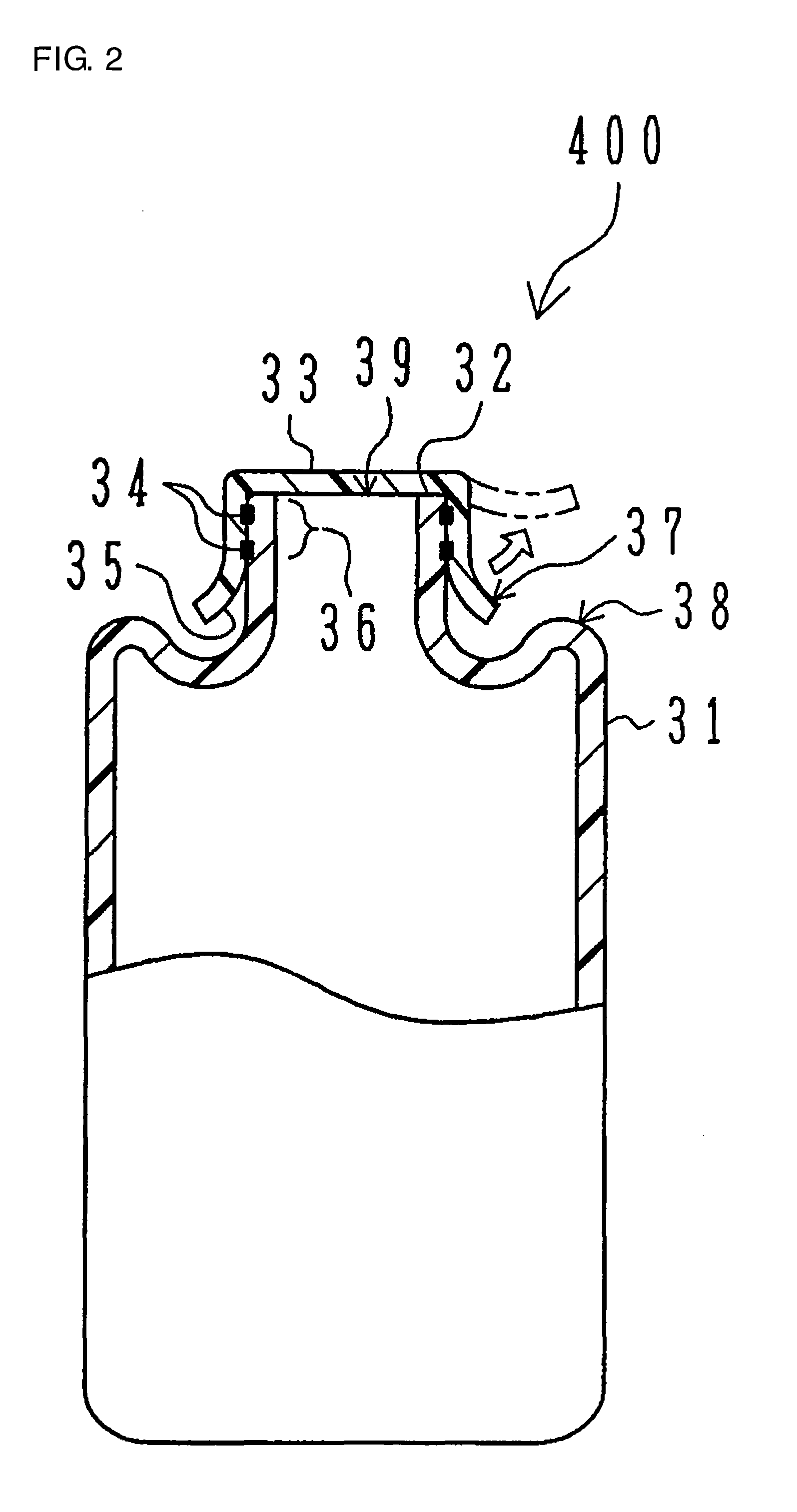
[0056] So long as the above-described connecting structure is satisfied, the shape of the lid portion and the shape of the container body, in particular the shape of the opening can be suitably changed. In the sealed container 100 of the first embodiment, the container body 1 has a shape in which the wall thereof is folded toward the inside of the container, and the opening 9 is formed at a position which is lower than the height of the folded portion. By giving the container body 1 this kind of shape, it forms a shape in which a straw can be easily inserted in the opening 9 at the time the lid is opened. The lid portion 3 has a size which at least covers the opening 9 in order to make it possible to seal the opening 9, and is formed so as to follow the shape of the outer wall surface of the container body 1 surrounding the opening 9. In this way, bonding surfaces which form the connected portion that forms the welded portion 4 are formed.

[0057] The outer edge portions of the openin...

second embodiment

[0073] On the other hand, in the case where the sealed container 200 is manufactured, after forming bonded surfaces by bonding an edge surface of the opening and an inner wall surface of the lid portion in order to make it possible for at least an inner wall surface of the peripheral portion of the opening from the inner wall surface of the container body to make contact with the container contents, the bonded surfaces are irradiated with a laser to form a welded portion.

[0074] In this regard, a process which provides a laser light absorbing portion in at least one of an outer wall surface of the peripheral portion of the opening or an inner wall surface of the lid portion, or in at least one of an edge surface of the opening or an inner wall surface of the lid portion, is preferably provided. Even if there are contours or undulations along the absorbing portion which make mechanical contact complicated, laser welding can be carried out with good precision. This is because the lase...


PUM

PropertyMeasurementUnit
Thicknessaaaaaaaaaa
Diameteraaaaaaaaaa
Lightaaaaaaaaaa

Abstract

It is an object of the present invention to provide a container in which it is difficult for liquid to drip at a mouth portion having a good touch sensation by forming a structure in which a welded portion that was laser welded in a sealed container does not form a flange, and to carry out the achievement of making polymer material unnecessary and making excessive material in the seaming portion unnecessary. Further, it is also an object to construct the lid and barrel of the vessel by using the same material, thereby facilitating the recycling of material. The sealed container in which a container body 1 having an opening 9 is sealed by a lid portion 3 which closes and covers said opening, comprising a welded portion 4, 14 in which an outer wall surface of a peripheral portion 2 of said opening or an edge 12 surface of said opening and an inner wall surface of said lid portion are laser welded in order to make it possible for at least an inner wall surface of the peripheral portion of said opening from an inner wall surface 6 of said container body to make contact with container contents.

Description

TECHNOLOGICAL FIELD [0001] The present invention is related to a sealed container in which contents such as foods and beverages and the like can be sealed with good sealing performance and there is little dripping of liquid at a mouth portion having a good touch sensation, and in particular to a sealed container having a welded portion that was laser welded and a manufacturing method thereof. PRIOR ART TECHNOLOGY [0002] As for a sealed container, for example, as for a beverage container, various containers such as bottles, cans, plastic containers and the like are known. In recent years, cans and plastic containers have been widely used from the viewpoint of convenience such as the quality of the handling performance thereof and the like. Of these, cans are in wide circulation because the container cost is low, the industrial speed is fast, the transportation efficiency is high and the like. These cans are usually formed from a cylindrical “body portion” which includes a bottom and ...

Claims


Application Information

Patent Timeline
IPC IPC(8): B65D41/00B29C65/00B29C65/16B65B7/28B65D1/02B65D8/02B65D53/00B65D77/20
CPCB29C65/1619B29C66/934B29C65/1654B29C65/1661B29C65/1677B29C66/112B29C66/1122B29C66/114B29C66/122B29C66/131B29C66/232B29C66/301B29C66/53461B29C66/542B29C66/65B29C66/652B29C66/8432B29C66/91216B29C66/939B29L2031/7158B65B7/2878B65D77/2024B65D2543/00425B65D2543/00842B29C65/1664B29C65/1683B29C66/91221B29C66/9131B29C66/836B29C65/1635B29C65/76B29C66/71B29C66/72323B29C66/72325B29C66/72343B29C66/73921B29C66/8322B29K2995/0027Y02W30/80B29K2023/06B29K2023/086B29K2023/12B29K2023/18B29K2023/38B29K2025/06B29K2025/08B29K2027/06B29K2027/08B29K2027/18B29K2033/12B29K2033/20B29K2055/02B29K2059/00B29K2067/00B29K2067/003B29K2067/006B29K2069/00B29K2077/00B29K2081/06B29K2096/005B65B7/28B65D1/02B65D11/08B65D53/00
Inventor NAKAYA, MASAKISHIRAKURA, AKIRA
Owner KIRIN BREWERY CO LTD
Why Eureka
Try Eureka