Ferroelectric memory device

a memory device and ferroelectric technology, applied in the field of ferroelectric memory devices, can solve the problems of deterioration of sensing margin and insufficient reduction of bit line capacitance, and achieve the effects of simplifying circuit structure, improving sensing margin, and reducing bit line capacitan

Inactive Publication Date: 2007-06-14
SEIKO EPSON CORP
View PDF4 Cites 7 Cited by
  • Summary
  • Abstract
  • Description
  • Claims
  • Application Information

AI Technical Summary

Benefits of technology

[0008] In accordance with an advantage of some aspects of the present invention, there are provided ferroelectric memory d

Problems solved by technology

However, according to a conventional device structure, when the device structure is miniaturized, an inter-wiring capacitance of adjacent ones of the bit lines greatly inf

Method used


Image

  • Ferroelectric memory device
  • Ferroelectric memory device
  • Ferroelectric memory device

Examples


Embodiment Construction

[0022] Preferred embodiments of the invention are described below with reference to the accompanying drawings.

[0023] 1. Structure of Ferroelectric Memory Device

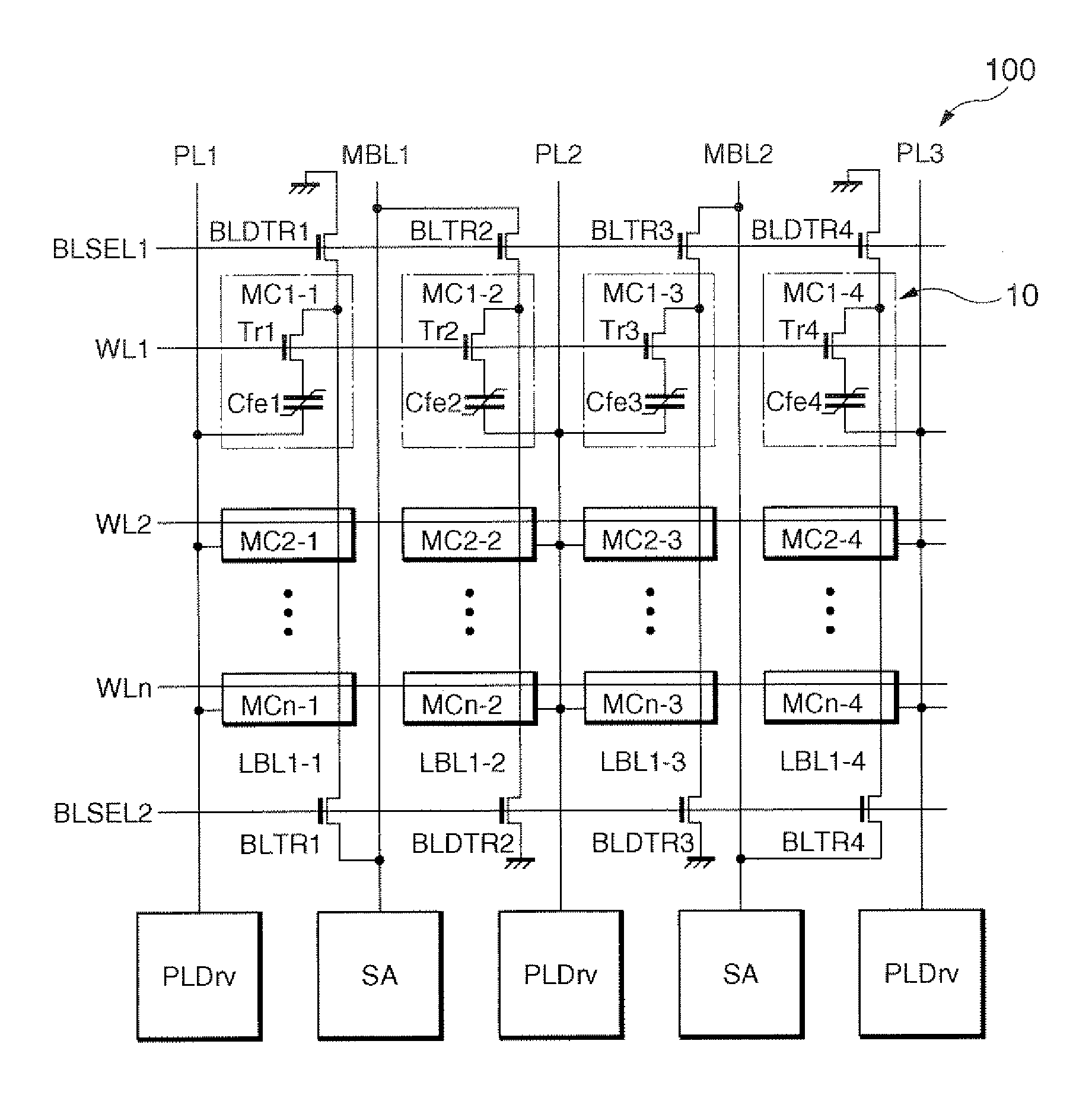
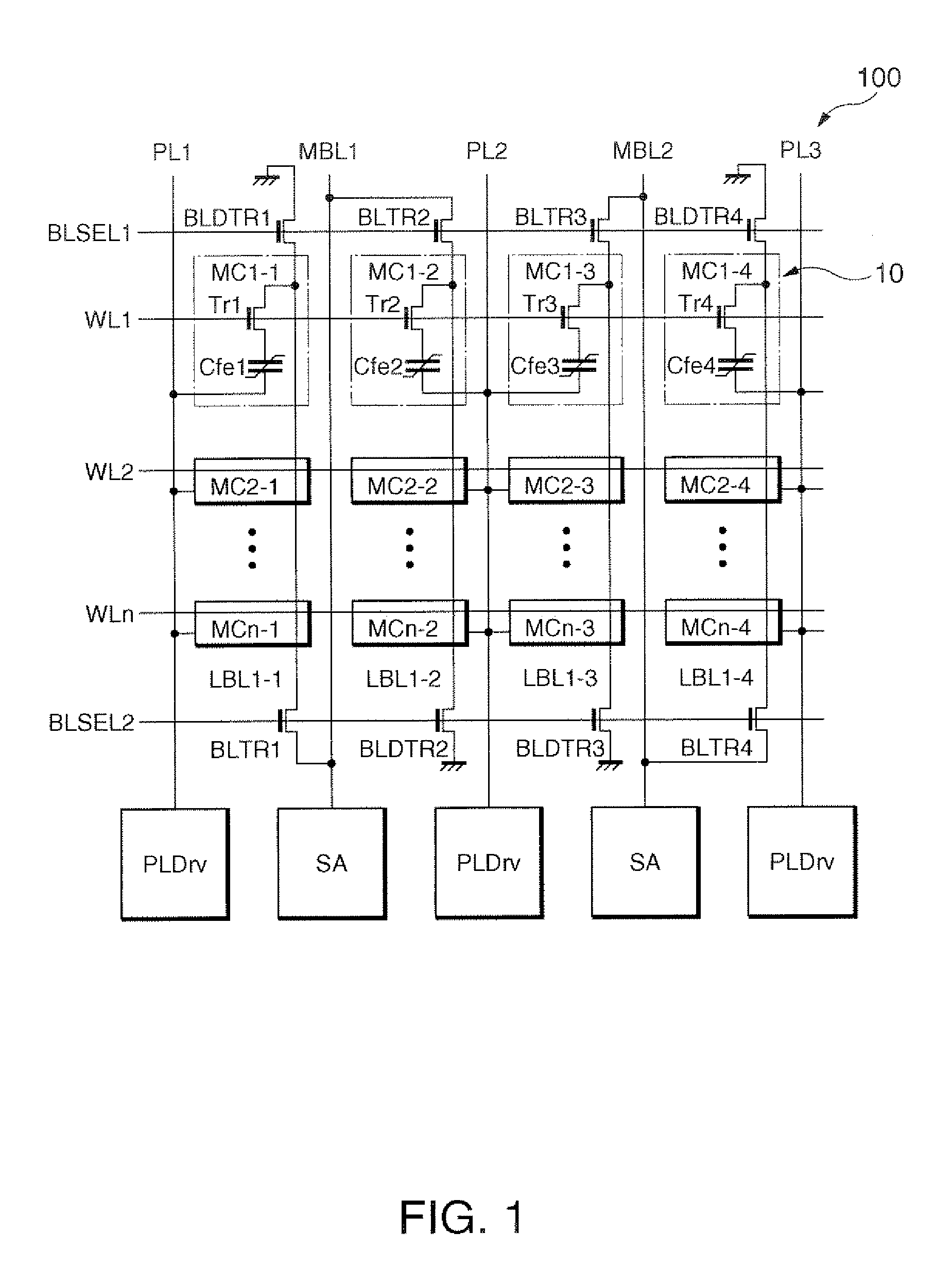
[0024]FIG. 1 is a circuit diagram of an example of a ferroelectric memory device in accordance with an embodiment of the invention.

[0025] A ferroelectric memory device (semiconductor memory device) 100 includes a memory cell array 10. The memory cell array 10 includes a plurality of memory cells MC1-1 through MCn-4, each including a ferroelectric capacitor. In the example shown in FIG. 1, for example, the memory cell MC1-1 includes a ferroelectric capacitor Cfe1, and a transistor Tr1 (for example, an n-type MOS transistor). The ferroelectric capacitor Cfe1 has one end connected one of a source and a drain (source / drain) of the transistor Tr1, and the other end connected to a plate line PL1. Also, the transistor Tr1 has a gate connected to a word line WL1, one of its source / drain connected to a local bit line LBL1-1, and th...


PUM


Abstract

A ferroelectric memory device includes memory cells using ferroelectric capacitors provided at intersections of local bit lines associated with a main bit line and word lines. The ferroelectric memory device includes: first and second local bit lines associated with a first main bit line; first and second connection transistors for connecting the first and second local bit lines to the first main bit line; first and second grounding transistors for grounding the first and second local bit lines; a first selection line that is commonly connected to gates of the first grounding transistor and the second connection transistor; and a second selection line that is commonly connected to gates of the first connection transistor and the second grounding transistor.

Description

[0001] The entire disclosure of Japanese Patent Application No. 2005-352433, filed Dec. 6, 2005 is expressly incorporated by reference herein. BACKGROUND [0002] 1. Technical Field [0003] The present invention relates to ferroelectric memory devices. [0004] 2. Related Art [0005] In a ferroelectric memory device, a potential appearing on a hit line at the time of normal reading becomes a potential that is voltage-divided by a ferroelectric capacitor and a bit line capacitance. Accordingly, to widen the potential difference of a bit line to secure a sufficient sensing margin, the bit line capacitance is required to be reduced. [0006] As a method to reduce the bit line capacitance, for example, a hierarchized bit line method is known. For example, Japanese laid-open patent application JP-A-2001-167591 describes an example of related art. In the hierarchized bit line method, a plurality of local bit lines, each being connected to a predetermined number of memory cells, is associated with...

Claims


Application Information

Patent Timeline
IPC IPC(8): G11C11/22
CPCG11C11/22
Inventor KOIDE, YASUNORIOZEKI, HIROYOSHI
Owner SEIKO EPSON CORP
Why Eureka
Try Eureka