Flexible optical device

a flexible optical device and waveguide technology, applied in the direction of fibre light guides, planar/plate-like light guides, instruments, etc., can solve the problems of background art that does not teach or suggest, background art also does not, etc., and achieve the effect of large area

Active Publication Date: 2007-06-14
OREE ADVANCED ILLUMINATION SOLUTIONS LTD +1
View PDF24 Cites 132 Cited by
  • Summary
  • Abstract
  • Description
  • Claims
  • Application Information

AI Technical Summary

Benefits of technology

[0026] The background art does not teach or suggest a flexible optical device capable of guiding a light while, at the same time, emitting a portion thereof through a predetermined region of its surface area. The background art also does not teach or suggest such a flexible optical device which is usefu

Problems solved by technology

The background art does not teach or suggest a flexible optical device capable of guiding a light while, at the same time, emitting a portion thereof through a predetermined region of its surface area.
The background art also does not teach or suggest such a flexible optical device which is useful for a variety of different applications in which the emitted light can be used for illuminating a sufficiently large area.
The background art also does not teach or suggest such a flexible optical device in which the emitted light constitutes readable information, such as, but not limit

Method used


Image

  • Flexible optical device
  • Flexible optical device
  • Flexible optical device

Examples


example 1

Flexible Materials and Indices of Refraction

[0149] Representative examples for polymers which may be used for any of layers 62, 64 and 66 include, without limitations, Latex, with index of refraction of 1.514; polyvinylchloride, with index of refraction of 1.539; Nitrile, with index of refraction of about 1.52; and Chloroprene (Neoprene), with index of refraction of 1.558. Other materials which may be used include, without limitation, poly(cis-isoprene), with index of refraction of 1.5191; Poly(2,3-dimethylbutadiene), with index of refraction of 1.525; Poly(dimethyl siloxane), with index of refraction of 1.4035; Ethylene / vinyl acetate copolymer-40% vinyl acetate, with index of refraction of 1.4760; Ethylene / vinyl acetate copolymer-30% vinyl acetate, with index of refraction of 1.4820, Poly(butadiene-co-acrylonitrile), with index of refraction of 1.52; natural rubber, with index of refraction of 1.514; and Poly(chloroprene), with index of refraction of 1.558. In addition, a high ref...

example 2

Prototype Waveguide

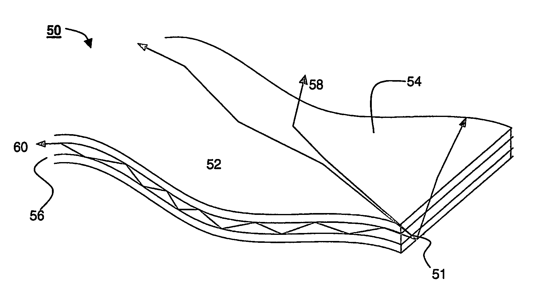
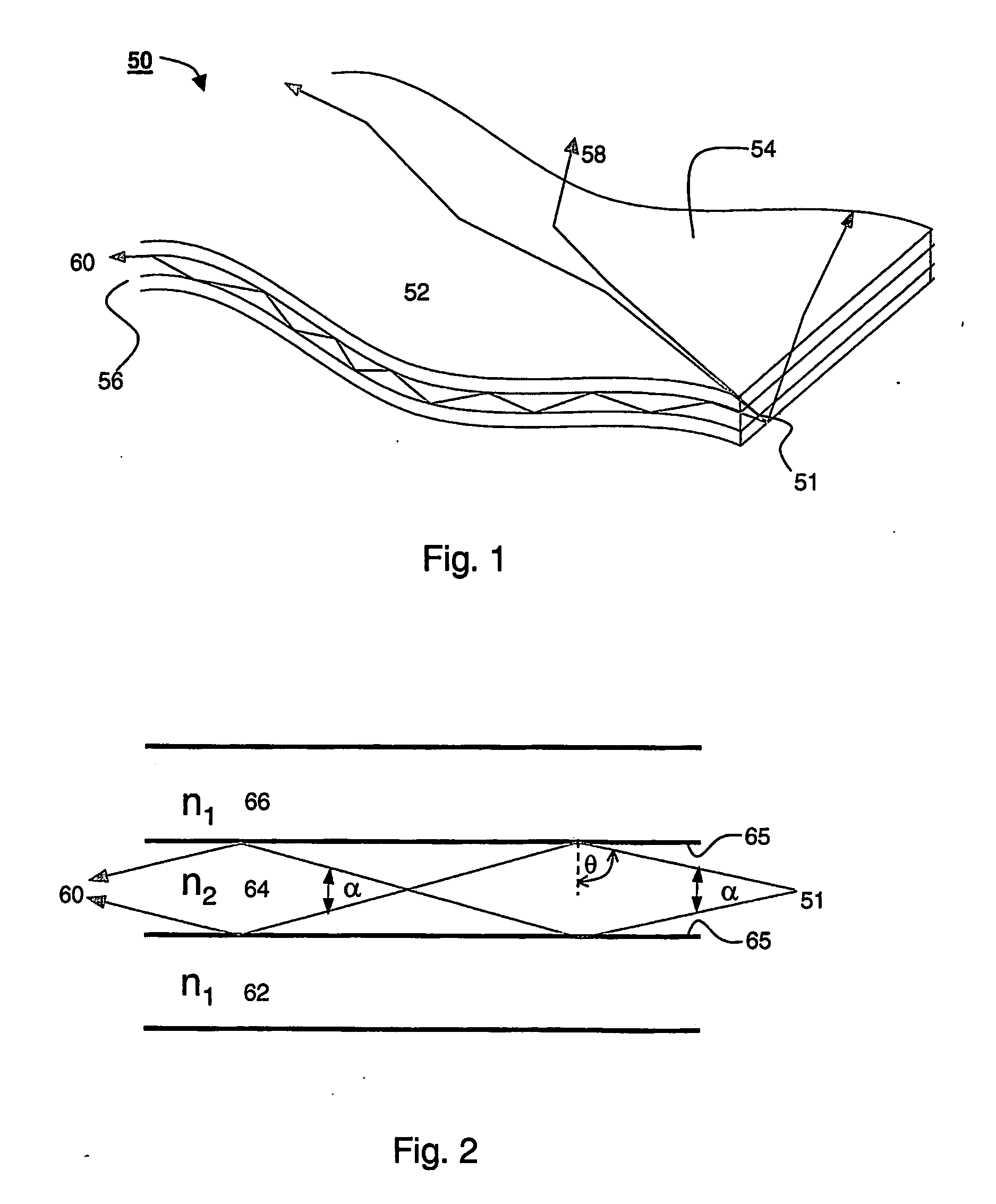
[0150] A prototype waveguide was manufactured, according to a preferred embodiment of the present invention. Specifically, the prototype waveguide included three layers (see FIG. 2), in which an intermediate layer (layer 64 in FIG. 2) served as the core waveguide and the external layers (layers 62 and 66 in FIG. 2) served as the clad. The intermediate layer was made of polyisoprene having a refractive index n2≈1.52, and each of the external layers was made of silicone rubber, having a refractive index n1≈1.40.

[0151] Polyisoprene and silicone rubber are biocompatible polymers which are commonly used in many medical devices, for example gloves. These materials have proven to be highly transparent to visible light, hence were suitable to serve as a core material for the prototype waveguide. When crosslinked both materials exhibit elasticity of about 500%, which is suitable for medical gloves.

[0152]FIG. 12 shows the coupling between the light source and the prototy...


PUM


Abstract

A flexible and optionally highly elastic waveguide capable of propagating and emitting light is disclosed. The flexible waveguide comprises a flexible material having a surface and an end, wherein a first portion of the light is emitted through at least a portion of the surface of the flexible waveguide, and a second portion of the light is emitted through the end. The flexible waveguide can be used, for example as an area illuminator for many applications. Additionally disclosed is a clothing device for providing illumination. The clothing device comprises clothing (or even optionally a sheet) and a light source for providing light. In one embodiment the clothing device comprises the flexible waveguide.

Description

FIELD OF THE INVENTION [0001] The present invention is of a flexible waveguide and its applications, and more. particularly, a device and system for directing light to illuminate an area. BACKGROUND OF THE INVENTION [0002] Illumination devices are useful in many areas of modern life, such as illumination of working area, illumination for the purpose of signaling and illumination carrying different type of information, such as an image and the like. [0003] In medical applications, the requirement for good illumination while operating, both in the operating room (OR) and in emergency and pre-hospital situations is one of the most critical elements of successful surgery and treatment. Until now, lighting techniques in have evolved around the use of strong ceiling and head mounted light fixtures. Even while using minimal invasive techniques, illumination and good access for light source are a critical element is the treatment's success. [0004] Unfortunately, the physical bodies of the s...

Claims


Application Information

Patent Timeline
IPC IPC(8): G02B6/10F21V8/00
CPCB82Y5/00B82Y10/00B82Y20/00G02B6/0008G02B6/0041G02B6/006G02B6/0061G02F1/011
Inventor FINE, ERAN
Owner OREE ADVANCED ILLUMINATION SOLUTIONS LTD
Why Eureka
Try Eureka