Fuel cell and method for fabricating same

a fuel cell and cell technology, applied in the field of fuel cells, can solve the problems of insufficient cell output for driving power sources, above miniaturization and weight saving of fuel cells, and achieve high hydrogen ion conductivity, high mechanical strength, and high output.

Inactive Publication Date: 2007-06-14
NEC CORP +1
View PDF4 Cites 29 Cited by
  • Summary
  • Abstract
  • Description
  • Claims
  • Application Information

AI Technical Summary

Benefits of technology

[0029] As described, in accordance with the present invention, the solid polymer fuel cell can be provided which realizes the high output, the miniaturization and the weight-saving.

Problems solved by technology

This cell output is not necessarily sufficient for the driving power source mounted on various devices.
While the unit cells may be stacked to secure the sufficient voltage for realizing the elevated cell voltage, the stacked unit cells are not preferable as the driving power source of a portable device requiring a thin configuration because the thickness of the entire cell increases by the stacking.
However, in this configuration, a wiring is necessary for connecting the cells to increase the cell size and to lower the degree of the cell integration.
However, a current collecting plate mounted on the rear of a catalyst layer in a conventional fuel cell significantly restricts the above miniaturization and the weight-saving of the fuel cell.
Accordingly, the fuel cell has a problem that the size in the direction of its thickness is enlarged.
The insufficient adhesion therebetween causes leak-out of fuel and leakage of current.

Method used


Image

  • Fuel cell and method for fabricating same
  • Fuel cell and method for fabricating same
  • Fuel cell and method for fabricating same

Examples


first embodiment

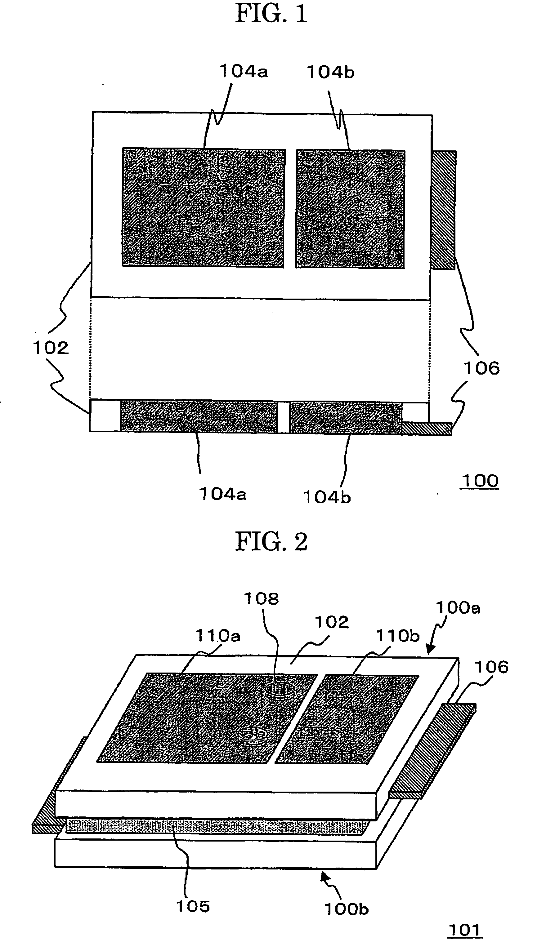
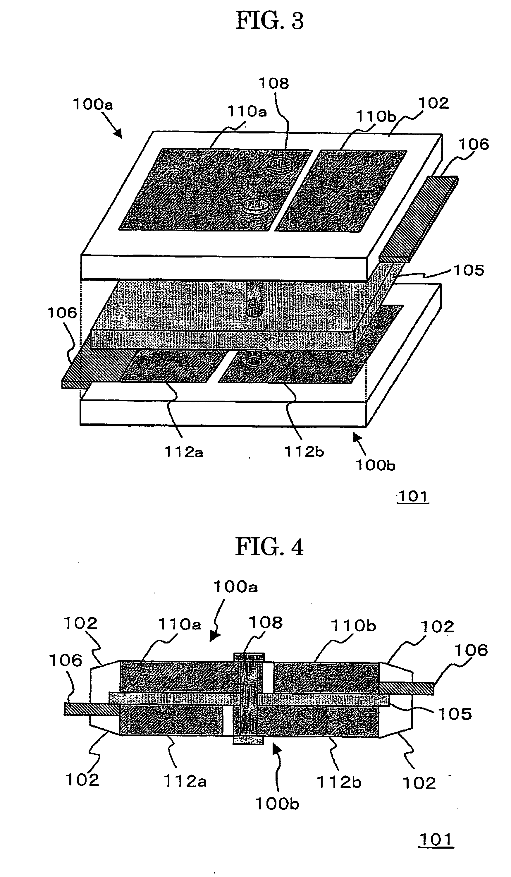
[0049] The present Embodiment exemplifies a fuel cell including two unit cells connected in series. FIG. 1 shows a schematic structure of an electrode sheet 100 constituting a fuel cell in accordance with the present Embodiment. In FIG. 1, the above drawing is an front elevation view and the bottom drawing is a side elevation view.

[0050] The electrode sheet 100 includes a plurality of electrodes 104a, 104b containing catalyst and disposed on a single plane, and a resin section 102 surrounding the electrodes. The electrode 104b is equipped with a draw-out electrode 106. The electrodes 104a, 104b are prepared by forming a catalyst layer on porous metal. While specific materials for forming the electrodes 104a, 104b and the resin section 102 are illustrated above, the electrodes 104a, 104b are made of foamed metal of SUS316 belonging to stainless steel and the resin section 102 is made of polyethylene in this Embodiment.

[0051] For example, the electrode sheet 100 can be fabricated as...

second embodiment

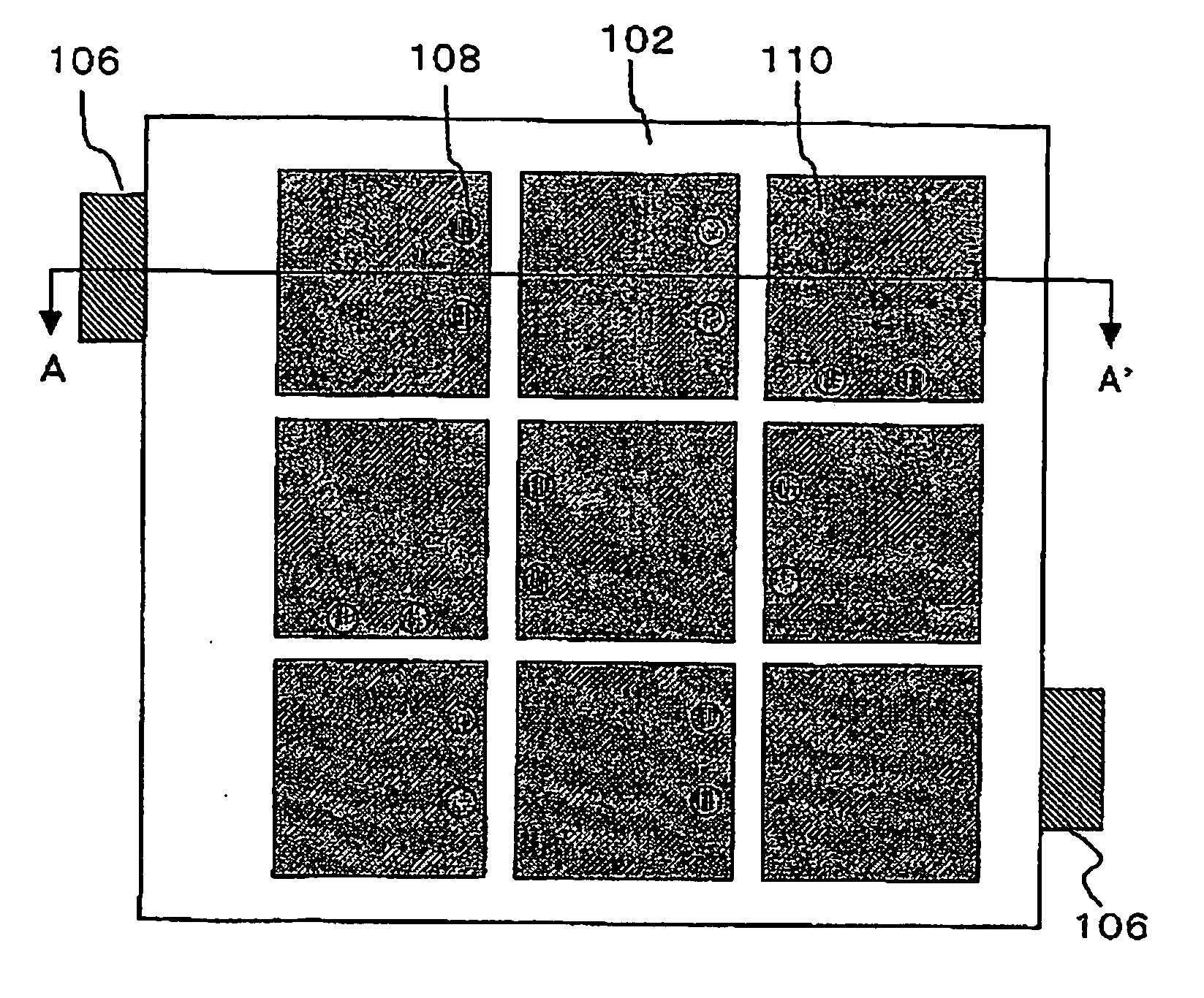
[0070] In this Embodiment, a fuel cell including electrodes and cells in matrix on a single plane is exemplified.

[0071] Before the description of the fuel cell of the present Embodiment, the structure of a conventional fuel cell will be shown. FIG. 6 is an example of a conventional fuel cell in an electrode-connection system. In the fuel cell, unit cells 120 are disposed in “2×2” in a resin section 102. A draw-out electrode 106 is mounted and connected to two adjacent unit cells 120 outside of an electrolyte membrane. In the fuel cell shown therein, the four unit cells are connected in series to take out the total output.

[0072] However, in this configuration, the draw-out electrodes outward extend around the resin section 102 so that there remains a problem regarding the miniaturization of the fuel cell and the higher integration. Further, since the respective unit cells are disposed along the respective edges of the resin section, each of the unit cells can be connected to the dr...

third embodiment

[0078] In the present Embodiment, as shown in FIG. 10, a metal frame 126 is disposed along the peripheries of the fuel electrode 110 and the oxidant electrode 112, and the rivet 108 is positioned through the metal frame to connect the cells. In this manner, a contact resistance between the rivet 108 and the cell can be reduced.


PUM

PropertyMeasurementUnit
open-circuit voltageaaaaaaaaaa
input voltageaaaaaaaaaa
porosityaaaaaaaaaa

Abstract

[Problems] Miniaturization and weight-saving of a fuel cell including a plurality of unit cells are intended together with higher integration of the unit cells. [Means for Solving Problems] A pair of electrode sheet 100a, 100b, each having a plurality of fuel electrodes 110a, 110b or a plurality of oxidant electrodes 112a, 112b supported by a resin section 102, are disposed on a single plane on the respective surfaces of a solid electrolyte membrane 105 to configure a plurality of unit cells. The fuel electrode and the oxidant electrode of the adjacent two unit cells existing on the respective surfaces of the solid electrolyte membrane are connected in series by using an electroconductive member penetrating the solid electrolyte membrane. Since the electroconductive member 108 extends along the stacking direction of the cell, no excess space is required to achieve the miniaturization of the fuel cell.

Description

TECHNICAL FIELD [0001] The present invention relates to a fuel cell having a solid electrolyte membrane on which a plurality of unit cells are disposed, and a method for fabricating the same. BACKGROUND ART [0002] A solid polymer electrolyte fuel cell is a power generator in which a fuel electrode and an oxidant electrode are bonded to the respective surfaces of an ion exchange membrane such as a perfluorosulphonic acid membrane acting as electrolyte. The power is generated by an electrochemical reaction which proceeds with the supply of hydrogen to the fuel electrode and of oxygen or air to the oxidant electrode. In order to induce the reaction, the solid polymer electrolyte fuel cell is generally configured by the ion exchange membrane; catalyst layers which are formed on both surfaces of the membrane and consist of a mixture including carbon particles supporting a catalyst substance thereon and a solid polymer electrolyte; gas diffusion layers (supply layers) made of a porous car...

Claims


Application Information

Patent Timeline
Patent Type & Authority Applications(United States)
IPC IPC(8): H01M8/10H01M4/86H01M4/88B05D5/12H01M8/02H01M8/24
CPCH01M8/006H01M8/0232H01M8/0247H01M8/0256H01M8/1002H01M8/1097H01M8/242H01M8/249Y02E60/521H01M8/1007Y02E60/50H01M8/2404
Inventor KIMURA, HIDEKAZUMANAKO, TAKASHIKAJITANI, HIROSHIKOBAYASHI, KENJIAKIYAMA, EIJIYOSHITAKE, TSUTOMUSATO, HIDEYUKIWATANABE, SUGURUNISHI, TAKANORIKUBO, YOSHIMIKATO, KOMEIISOBE, TAKESHIWADA, MASAHIROKANDA, EIKOHAMADA, KAZUICHI
Owner NEC CORP
Why Eureka
Try Eureka