Method and apparatus for delayed pericardial drainage

a technology of pericardial drainage and delay, which is applied in the direction of catheters, wound drains, suction devices, etc., can solve the problems of incomplete fluid drainage, cardiac tamponade, and fluid production

Inactive Publication Date: 2007-06-14
MEDICAL INSTR
View PDF3 Cites 28 Cited by
  • Summary
  • Abstract
  • Description
  • Claims
  • Application Information

AI Technical Summary

Benefits of technology

[0011] The cannula of the present invention along with its internal shaft is positioned inside the pericardial cavity at the end of surgery along with other standard chest drains. Placement is accomplished by routing the cannula from the pericardial cavity, through the patient skin, and extending outside the body. The cannula is fixed to the patient skin and left in situ throughout all the postoperative period. The cannula of the present invention is to be left in situ after all standard chest tubes have been removed according to the standard protocols. Should a delayed pericardial effusion arise (most frequently for those patients who need to be on anticoagulant therapy, or those with a strong inflammatory response), simply removal of the internal shaft of the cannula will allow an immediate drainage of excess of fluid without the need for chest re-exploration or re-positioning of other drainage catheters.

Problems solved by technology

An excess of fluid into the pericardial cavity might result in compression of the cardiac chambers with consequent impairment of the pump function causing a condition called cardiac tamponade.
However, in some cases the fluid build up might start or continues after pericardial or chest tubes have been removed, In other cases the pericardial or chest tubes might have clogged early after surgery causing an incomplete fluid drainage.
In other cases late lysis of clotted blood might be the cause of fluid production.
This latter procedure is usually accomplished by X-ray or ultrasound guidance and involves a risk of iatrogenic trauma to the patient.

Method used


Image

  • Method and apparatus for delayed pericardial drainage
  • Method and apparatus for delayed pericardial drainage
  • Method and apparatus for delayed pericardial drainage

Examples


Embodiment Construction

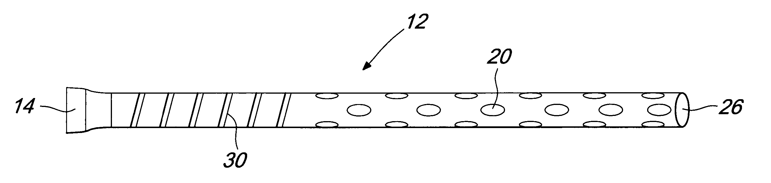
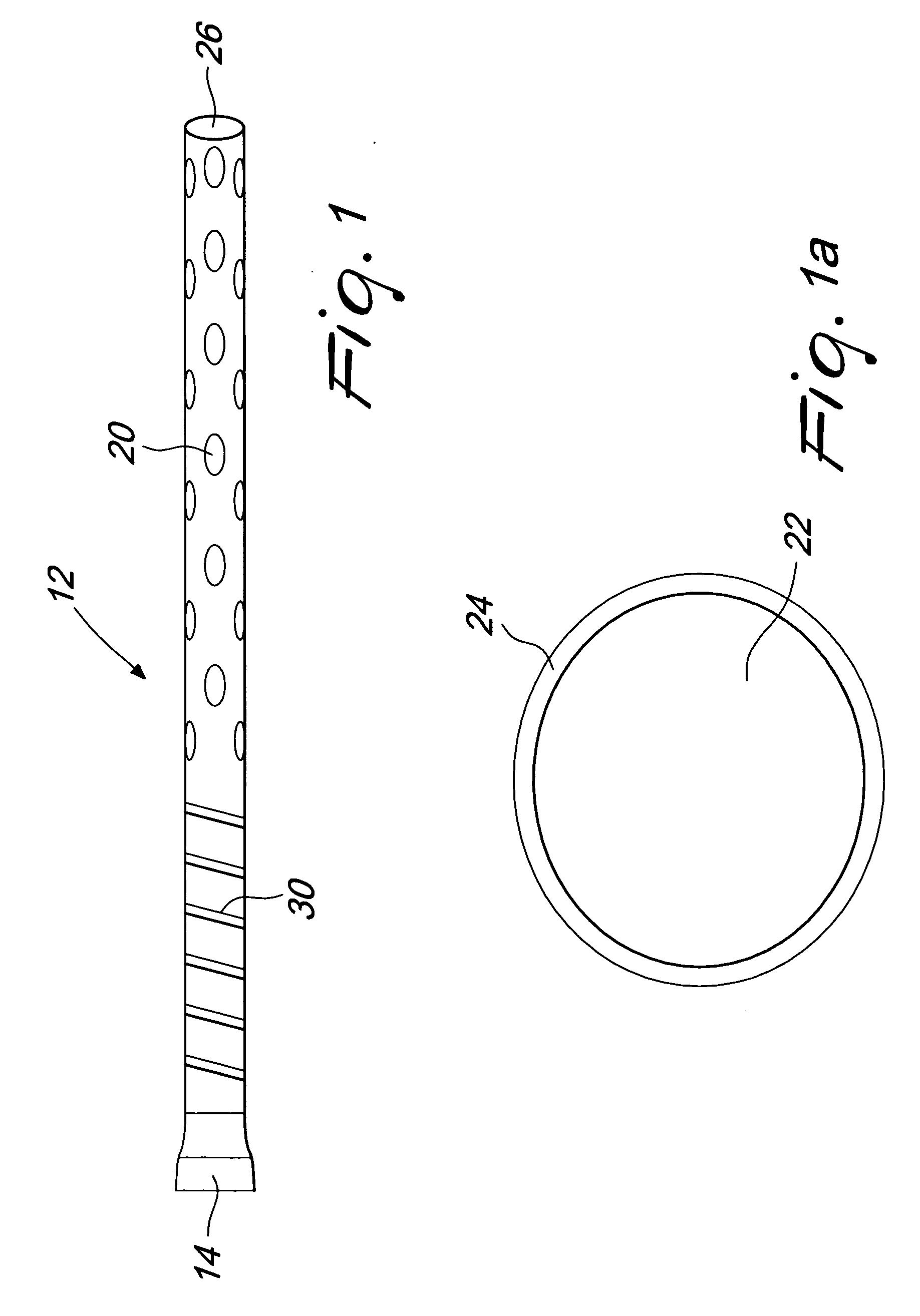
[0018]FIG. 1 illustrates a tubing 12 that, along with an internal shaft, forms a cannula 10 of the present invention. The tubing 12 has a proximal end 14 to be connected with an external vacuum or pumping system and a distal end with a plurality of drainage holes 20 and an open ending 26. The tubing 12 preferably comprises a stiffening wire 30.

[0019]FIG. 1a illustrates the cross sectional view of the tubing 12 that comprises a drainage lumen 22 and a wall 24. The tubing material may be selected from any polymer such as, but not limited to, polyvinyl chloride, polyurethane, polyethylene and the like.

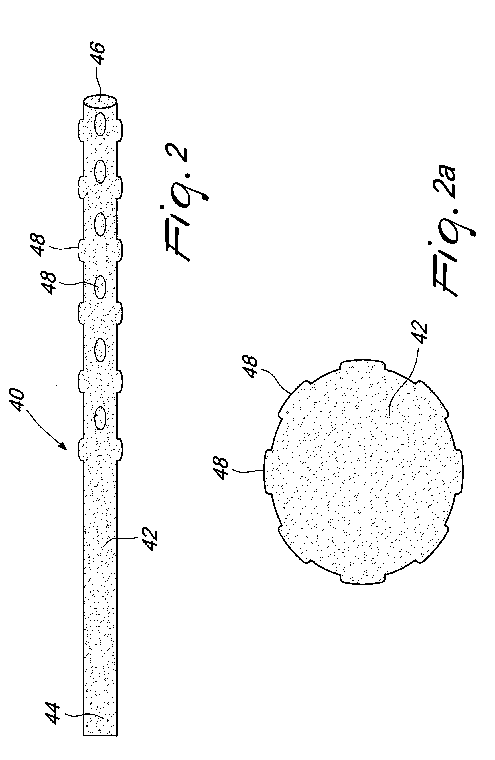
[0020] The tube 12 is, preferably, transparent or semitransparent. At least a portion of the tubing 12 is preferably stiffened with a helical winding of material such as stainless steel, nitinol and the like. The stiffening 30 could also be provided using corrugations in the tubing 12 or by addition of a strong polymer such as glass-filled polycarbonate instead of the helical winding. T...


PUM


Abstract

Device for placement in the thoracic cavity of a patient. The device is a cannula, tube or catheter for pericardial drainage and serves as a conduit for drainage of excessive fluid in the pericardial cavity to a receptacle outside the body. The device is placed in the pericardial cavity at the time of surgery and is used for drainage of fluid collection that is formed at a later stage when all other drainage tubes have been already removed or are clogged by organic material. The device incorporates a system for preventing that any clog or material might close all fenestrations that are present in the tube at a plurality of sites.

Description

[0001] The present invention related to a catheter, tube or cannula for delayed drainage of blood, fluid or contaminants from the pericardial cavity. [0002] The field of this invention is cardiac surgery, thoracic surgery, trauma and critical care. BACKGROUND OF THE INVENTION [0003] Chest drainage tubes or pericardial drainage tubes are used following cardiac, thoracic surgery, chest trauma or for specific medical conditions. The purpose of a chest or pericardial drainage is to remove build-up of excessive body fluid (blood or serum) from the pericardial and mediastinal cavity. An excess of fluid into the pericardial cavity might result in compression of the cardiac chambers with consequent impairment of the pump function causing a condition called cardiac tamponade. [0004] Current pericardial or chest drainage cannulae, also called pericardial or chest tubes, drainage catheters or drainage cannulae are flexible polymer tubes, placed into the chest cavity and extending outside the p...

Claims


Application Information

Patent Timeline
Patent Type & Authority Applications(United States)
IPC IPC(8): A61M27/00
CPCA61M27/00A61M27/002A61M27/008A61M2025/0018A61M2025/006A61M2025/0079A61M2027/004
Inventor DE PAULIS, RUGGERO
Owner MEDICAL INSTR
Why Eureka
Try Eureka