Methods and systems for measuring a rate of change of requency

a technology of frequency change and frequency, applied in the field of measuring frequency, can solve the problems of erroneous frequency determination, general undesirable operation of turbines above or below predetermined mechanical resonance limits and/or frequencies, and costly premature system shutdown

Inactive Publication Date: 2007-06-14
GENERAL ELECTRIC CO
View PDF42 Cites 28 Cited by
  • Summary
  • Abstract
  • Description
  • Claims
  • Application Information

AI Technical Summary

Problems solved by technology

For example, it may be generally undesirable to operate a turbine above or below predetermined mechanical resonance limits and / or frequencies.
However, at least some of such known measuring techniques may be sensitive to noise on the power lines because of large frequency changes naturally occurring in the utility network, voltage spikes, and / or voltage glitches, which may be detected as zero crossings of the voltage waveform thereby leading to erroneous frequency determinations.
Moreover, non-fundamental components of the electrical power system may produce signals detected as zero crossings, which may also produce erroneous frequency results.
Improper and / or erroneous frequency determinations may lead to costly premature system shutdown if the system frequency does not actually exceed the predetermined frequency limits and the frequency monitor indicates it does exceed the limits.
Moreover, if the system frequency does actually exceed the predetermined limits and the frequency monitor indicates it does not exceed the limits, improper and / or erroneous frequency determinations may result in damage to a prime mover and / or other electrical power system components.
Furthermore, non-synchronous generators may be interconnected, resulting in problems described above, for example if the frequency monitor erroneously indicates that the frequencies of the generators are the same.
At least some known frequency measurement techniques that use zero crossing measurements may also be less accurate than desirable, for example if the measured signal is not a perfect sinusoid.
However, at least some known frequency measurement techniques that use zero crossing measurements may include a non-detection zone (NDZ), and therefore may not be able to prevent unintentional islanding under power match conditions.

Method used


Image

  • Methods and systems for measuring a rate of change of requency
  • Methods and systems for measuring a rate of change of requency
  • Methods and systems for measuring a rate of change of requency

Examples


Embodiment Construction

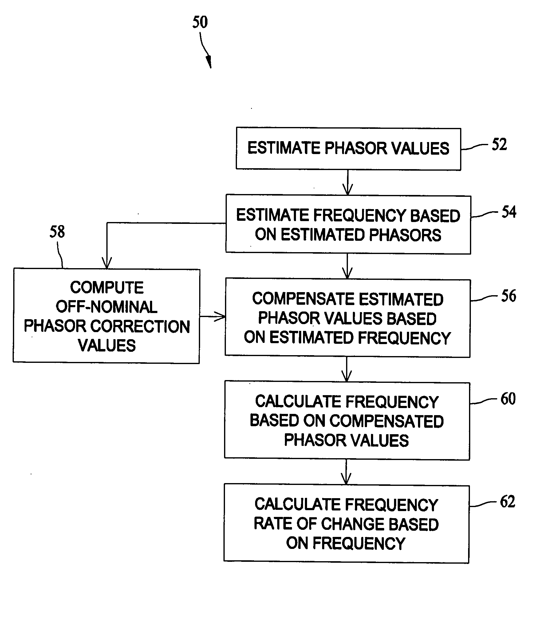
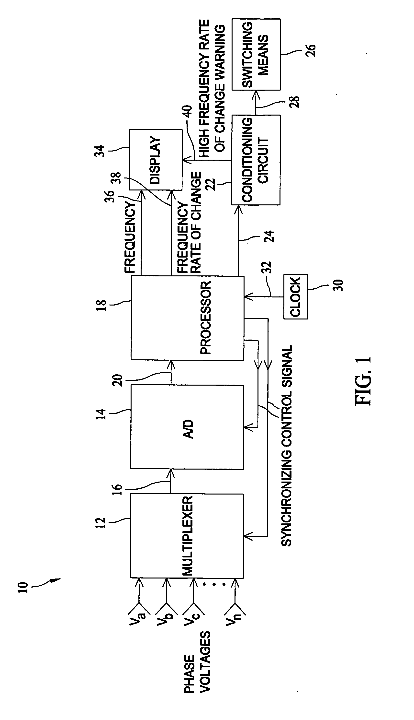
[0012] Although the systems and methods described and / or illustrated herein are described and / or illustrated with respect to an electrical power system, and more specifically single-phase and three-phase electrical power systems, practice of the systems and methods described and / or illustrated herein is not limited to single-phase or three-phase electrical power systems, nor electrical power systems generally. Rather, the systems and methods described and / or illustrated herein are applicable to determining the frequency and / or frequency rate of change from a desired frequency for any periodic function or motion from which a parameter representative of the periodic function or motion is available to define a phasor that represents the function and / or motion. As used herein, a phasor is intended to mean a quantity having both magnitude and direction, such as, but not limited to, a +jb (rectangular coordinates) and Ze−jθ (polar coordinates), used to represent a time-varying quantity. S...


PUM


Abstract

A method for measuring a rate of change of frequency includes estimating at least one phasor value, estimating a frequency based on the estimated at least one phasor value, compensating the estimated at least one phasor value based on the estimated frequency, calculating a frequency based on the compensated at least one phasor value, and calculating a rate of change of the calculated frequency based on the calculated frequency.

Description

BACKGROUND OF THE INVENTION [0001] This invention relates generally to measuring frequency, and more particularly to methods and systems for measuring a rate of change of frequency. [0002] Mechanical frequency limits are sometimes established to protect an electrical generator prime mover, typically a turbine. For example, it may be generally undesirable to operate a turbine above or below predetermined mechanical resonance limits and / or frequencies. Accordingly, it may be important to monitor an operating frequency of the turbine. An electrical signal frequency, indicative of turbine mechanical frequency, may therefore be monitored to determine whether the frequency is within predetermined electrical frequency limits, and thereby facilitate operating the turbine within the predetermined band of mechanical frequencies. Moreover, before interconnecting loads supplied by different generators, it may be desirable that both generators are operating at the same electrical frequency to pr...

Claims


Application Information

Patent Timeline
Patent Type & Authority Applications(United States)
IPC IPC(8): G01R23/00
CPCG01R23/00G01R29/18
Inventor PREMERLANI, WILLIAMZHOU, RUI
Owner GENERAL ELECTRIC CO
Why Eureka
Try Eureka