Radial engine power system

a power system and radial engine technology, applied in the direction of reciprocating piston engines, positive displacement engines, combustion engines, etc., can solve the problems of reducing unable to exploit certain characteristics of internal combustion engines, and affecting the service life of conventional engines

Inactive Publication Date: 2007-06-21
GREENWELL GARY A
View PDF37 Cites 51 Cited by
  • Summary
  • Abstract
  • Description
  • Claims
  • Application Information

AI Technical Summary

Benefits of technology

[0008] The present invention combines the advantages of a rotary block, reciprocating piston internal combustion engine with an energy storage system to improve on benefits which accrue from today's hybrid vehicle arrangements. To this end, the present invention uses an improved rotary block radial engine in combination with one or more energy storage systems which can release power independently of power being developed within the engine by combustion of the fuel at any one instant in time. This engine provides a large rotating flywheel mass with no attendant increase in overall mass, minimal reciprocating load of pistons, and frequency in firing of a two stroke cycle engine.
[0010] When power is not required, a mechanical adjustment to the crankshaft is made. This adjustment permits the engine block and pistons to rotate without imposing a driving force on the crankshaft. Thus that energy originating in the engine and presently taking the form of kinetic energy may be conserved without dissipation which otherwise would be caused by decelerating the engine back to the stationary condition. As a consequence, combustion which would merely waste fuel when idling may be discontinued. The engine block with its relatively great mass would continue to rotate. This permits power to be derived from a flywheel effect and also eliminates the step of rotating the internal combustion engine when restarting it.
[0012] It is an object of the invention to utilize a rotary radial engine having a stationary crankshaft and minimal parasitic piston reciprocation losses as a prime mover in a hybrid power plant which incorporates selectively releasable energy storage.
[0017] It is an object of the invention to provide improved elements and arrangements thereof by apparatus for the purposes described which is inexpensive, dependable, and fully effective in accomplishing its intended purposes.

Problems solved by technology

Considering now the internal combustion engine which is selected for use with hybrid vehicles, contemporary practice is limited to those engines wherein at least one and usually a plurality of pistons are reciprocatingly disposed within bores or cylinders formed in a stationary structural engine block.
While these engines are entirely operable, they fail to exploit certain characteristics which are available in internal combustion engines.
While conventional engines can be fitted with suitably heavy flywheels or other rotatable masses, this comes at a detrimental cost in conventional engines.
That is, total weight of the engine is increased.
A drawback of the engine in the environment of small aircraft was the gyroscope effect developed by the rotating mass, which introduced difficulties in steering the aircraft.

Method used


Image

  • Radial engine power system
  • Radial engine power system
  • Radial engine power system

Examples


Embodiment Construction

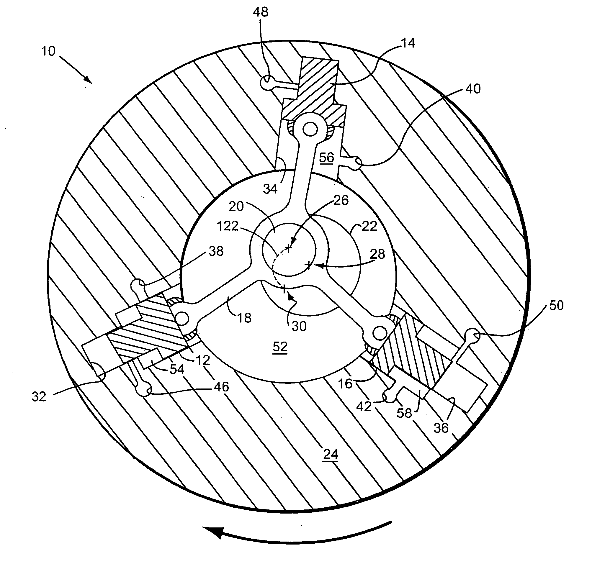
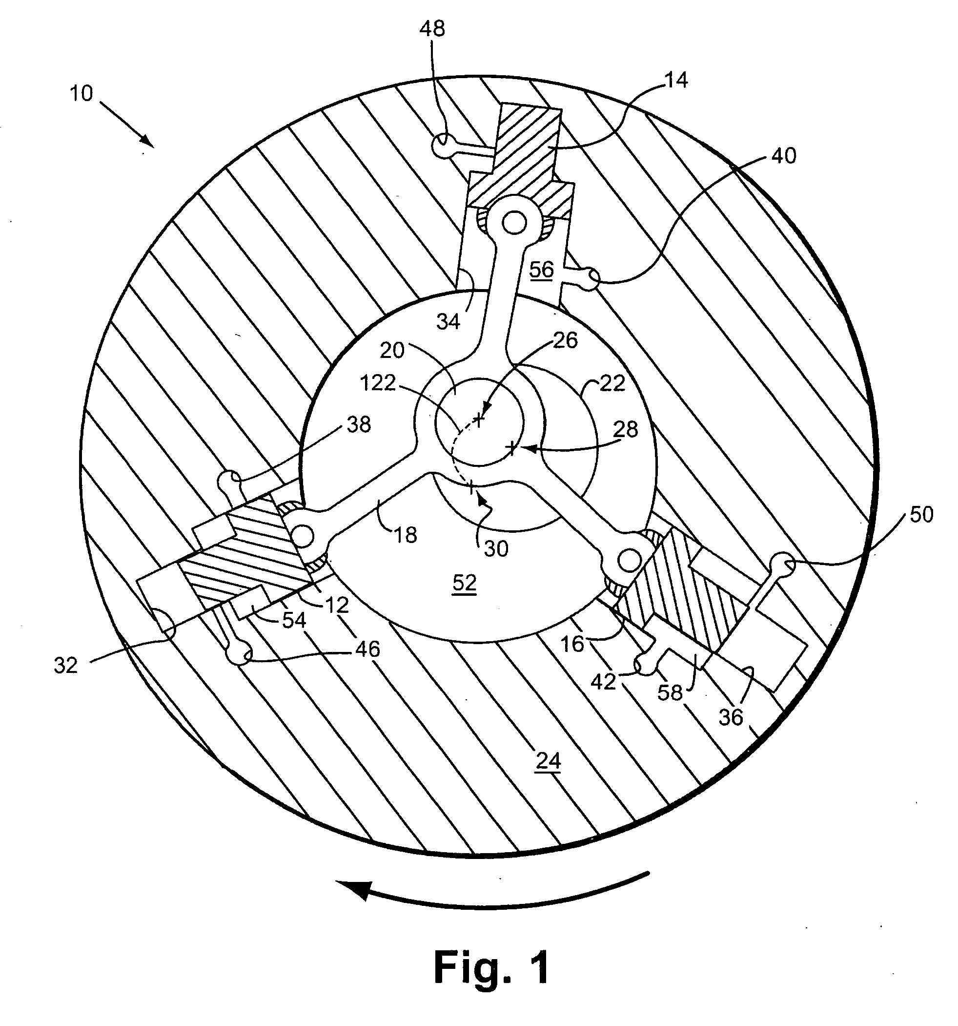
[0032] The present invention combines the attributes of a radial rotary engine 10 with an energy storage system. Referring first to FIG. 1, basic operation of a radial rotary engine will be summarized. A plurality of pistons 12, 14, 16 are pivotally connected to a multi-armed connecting rod 18 which in turn encircles a journal 20 of a crankshaft 22. Journal 20 is eccentrically located on crankshaft 22. Crankshaft 22 is located inside annular cylinder block 24. Three axes 26, 28, 30 are seen in the top plan view of FIG. 1. Axis 26 indicates the center line of journal 20. Axis 28 indicates the center line of crankshaft 22. Axis 30 indicates the rotational axis of cylinder block 24. In a radial rotary engine, crankshaft 22 is fixed to its associated vehicle (not shown in its entirety). As will be explained, cylinder block 24 rotates about stationary crankshaft 22. Pistons 12, 14, 16 and connecting rod 18 rotate in tandem with cylinder block, but in respective compound motions. Pistons ...


PUM


Abstract

A power plant utilizing a radial rotary engine and incorporating onboard energy storage. The engine is of the type utilized in pre-World War I aircraft, but with certain modifications. The energy storage system exploits the flywheel effect inherent in these engines and optionally also includes auxiliary energy storage in other forms, such as compressed air or electrical. Using a continuously variable transmission enables advantageous use of engine inertia in a coast down mode of driving.

Description

BACKGROUND OF THE INVENTION [0001] This application claims the benefit of U.S. Provisional Patent Application Ser. No. ______ filed on May 13, 2004 as Attorney Docket Number D2GRE001.11.FIELD OF THE INVENTION [0002] The present invention is directed to a power system including a radial internal combustion engine serving as a prime mover, and an associated energy storage system which cooperates with the radial engine. DESCRIPTION OF THE PRIOR ART [0003] Internal combustion engines have long been used to power transport vehicles on land, in and on water, and in the air. Initially, internal combustion engines were directly connected to wheels, propellers, and other elements of a vehicle which acts on an environmental medium to effect propulsion. In some applications, power generated by internal combustion engines has been transformed before bearing on the propulsion effecting elements of the vehicle. For example, diesel electric railway locomotives have diesel engines serving as prime ...

Claims


Application Information

Patent Timeline
Patent Type & Authority Applications(United States)
IPC IPC(8): F02B75/26F02B57/00F01B13/04
CPCF01B3/0035F01B13/04F02B53/02Y02T10/17Y02T10/12
Inventor GREENWELL, GARY A.
Owner GREENWELL GARY A
Why Eureka
Try Eureka