Discharge lamp lighting apparatus and lamp system using the lighting apparatus

a technology for lighting apparatus and discharge lamps, which is applied in the direction of electric variable regulation, process and machine control, instruments, etc., can solve the problems of large size of lighting apparatus and shorten and achieve the effect of shortening the life of discharge lamps

Inactive Publication Date: 2007-06-21
MATSUSHITA ELECTRIC WORKS LTD
View PDF11 Cites 26 Cited by
  • Summary
  • Abstract
  • Description
  • Claims
  • Application Information

AI Technical Summary

Benefits of technology

[0020] In this arrangement, the control unit includes electrode heating amount setting means which sets an alternation time of the output power to be supplied to the discharge lamp in an electrode heating period for actuation of the discharge lamp to be longer than an alternation time thereof in a steady lighting period thereof, and which increases the alternation time in the electrode heating period depending on a lowering degree of a lamp power or a lamp current supplied to the discharge lamp.
[0021] According to

Problems solved by technology

However, in that method, stress to the discharge lamp and the lighting apparatus is increased, causi

Method used


Image

  • Discharge lamp lighting apparatus and lamp system using the lighting apparatus
  • Discharge lamp lighting apparatus and lamp system using the lighting apparatus
  • Discharge lamp lighting apparatus and lamp system using the lighting apparatus

Examples


embodiment 1

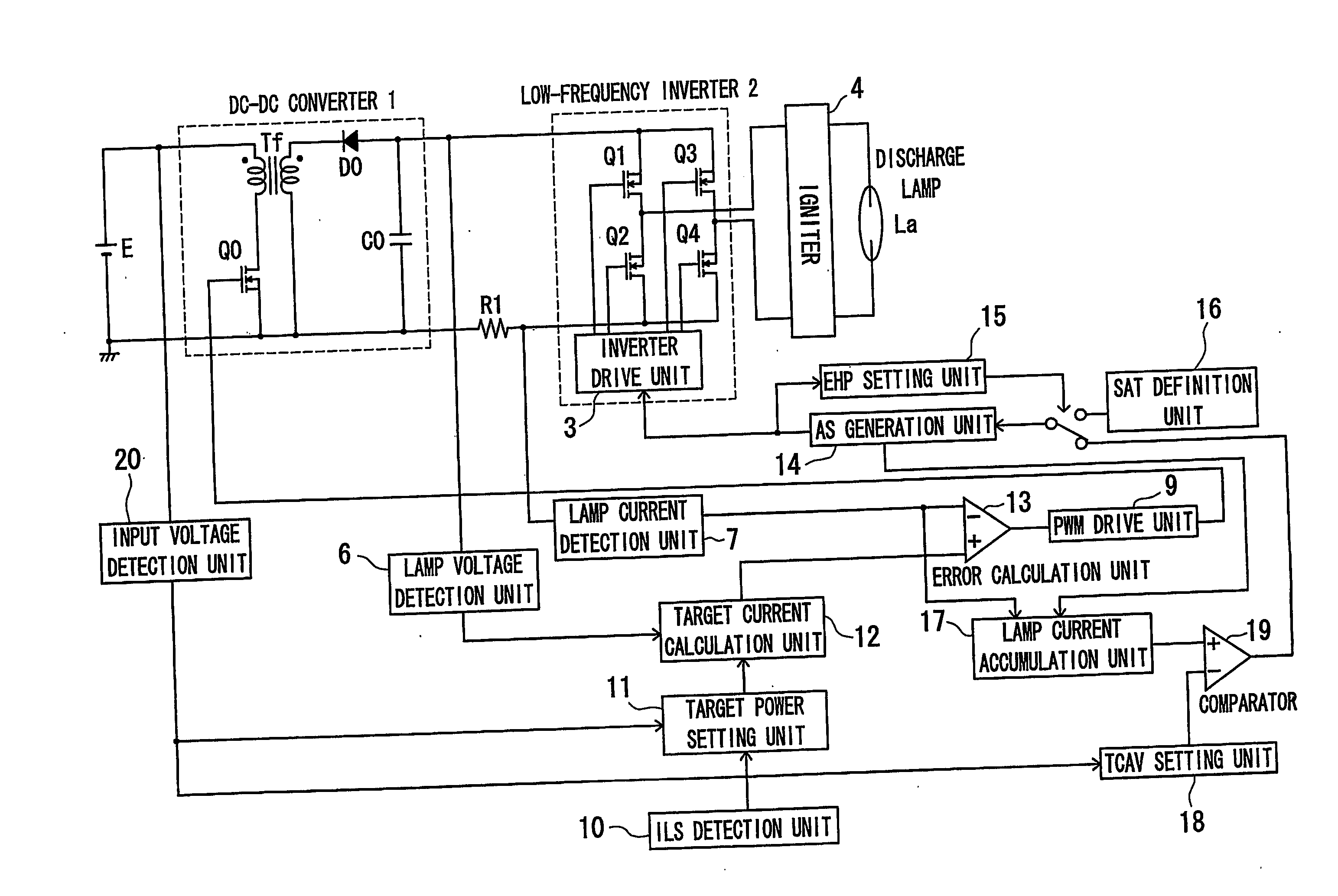
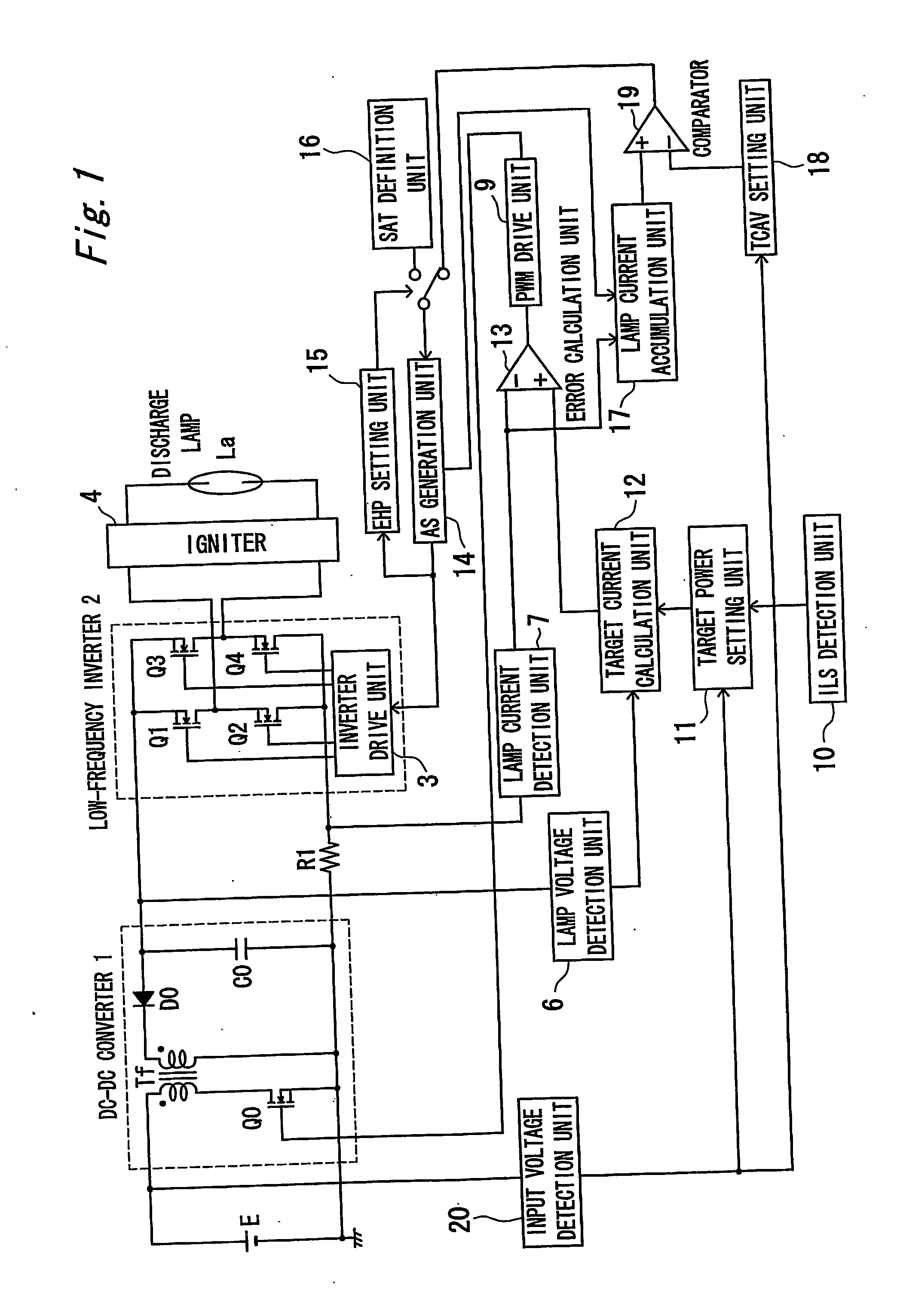
[0053]FIG. 1 is a circuit diagram showing an embodiment 1 of a discharge lamp lighting apparatus according to the present invention. In FIG. 1, reference character E designates a DC power supply which is a car battery (14V, for example) and the like. However, a commercial AC power supply may be used under the condition of being rectified and smoothed.

[0054] Reference numeral 1 designates a DC-DC converter, which constitutes a power conversion unit in a first aspect of the present invention. Although an FET is illustrated as a switching element Q0, other type of a switching element, for example, IGBT may be also used therefor. The DC power is converted through a transformer Tf by turning on / off the switching element Q0. Although a flyback type is illustrated as a circuit mode, it may be another type. An output of the transformer Tf is rectified by a diode DO and the smoothed DC voltage is obtained by a capacitor C0. In addition, according to the illustrated circuit, although a negat...

embodiment 2

[0079]FIG. 5 is a circuit diagram showing a second embodiment 2 of a discharge lamp lighting apparatus according to the present invention. In this embodiment, an alternation signal generation unit 14 receives an output of an input voltage detection unit 20 and when the input voltage is lowered, generation of an alternation signal is delayed by a predetermined time. Similar to the embodiment 1, the predetermined delay time may be changed step by step according to the lowering of the input voltage, or the predetermined delay time may be gradually elongated as the input voltage becomes lower.

[0080] According to the above constitution and the operations, the alternation time is not set by a lamp current accumulated value for an electrode heating period (although it is not shown), and there is a merit in which application is easy even when the alternation time is set depending on an output of an initial lamp state detection unit 10, for example.

[0081] Meanwhile, although an output of a...

embodiment 3

[0083]FIG. 6 is a circuit diagram showing an embodiment 3. The same reference numerals and signs are allotted to the same components as in the embodiment 1 shown in FIG. 1 and the descriptions thereof are omitted and only difference points will be described. As shown in FIG. 6, a temperature detection unit 21 detects a temperature of a lighting apparatus. For example, a thermistor is used for detecting a temperature of a portion on a mounting substrate. A target power setting unit 11 receives a detected temperature value output of the temperature detection unit 21 and sets an upper limit in setting a target power. Thus, when the temperature is high, the target power setting unit 11 sets the target value so as not to be greater than the upper limit in order to limit an output power. That is, in order to prevent element stress, when the detection temperature becomes higher than a normal temperature i.e., an upper limit is 105° C., for example), the output power after a discharge lamp ...


PUM


Abstract

In a discharge lamp lighting apparatus, a power supplied to a discharge lamp La through a DC-DC converter 1 and an inverter 2 is controlled depending on detection results of a lamp voltage detection unit 6 and a lamp current detection unit 7, and in an electrode heating period an alternation time of an output to the discharge lamp when starting actuation of the discharge lamp is set longer than an alternation time in a steady lighting period, and the alternation time in the electrode heating period is increased depending on lowering of a supply power or current to the discharge lamp. Thus, even when a lamp current is suddenly changed, the discharge lamp is prevented from going off at the time of polarity inversion without lowering a life.

Description

TECHNICAL FIELD [0001] The present invention relates to an apparatus for lighting a high-voltage discharge lamp such as a metal halide lamp, and more particularly, to a discharge lamp lighting apparatus which is needed when a car headlight and the like is instantaneously lightened, and also relates to a lamp system using the lighting apparatus. BACKGROUND ART [0002]FIG. 30 shows a conventional example 1 of a lighting apparatus disclosed in Document 1 (Japanese Patent Unexamined Laid-open Publication No. 9-73991). The conventional example 1 of the lighting apparatus comprises a DC power supply E, a lighting switch S, a DC-DC converter 1, a low-frequency inverter 2, an igniter 4, a discharge lamp La, and a control circuit 5. The control circuit 5 controls an output power so as to be a set value by detecting an output voltage and an output current of the DC-DC converter 1 as a lamp voltage and a lamp current of the discharge lamp La, calculating a lamp power from the detection results,...

Claims


Application Information

Patent Timeline
IPC IPC(8): H05B37/02H05B41/24H05B41/282H05B41/288H05B41/292H05B41/38
CPCH05B41/2883H05B41/2928H05B41/388Y02B20/208Y02B20/00
Inventor SUGANUMA, KAZUTOSHIKANBARA, TAKASHITANAKA, TOSHIFUMI
Owner MATSUSHITA ELECTRIC WORKS LTD
Why Eureka
Try Eureka