Magnetic sensing device including a sense enhancing layer

a sensing device and sense enhancement technology, applied in the field of magnetic sensors, can solve the problems of reducing the performance of the device and the difficulty of processing such a devi

Active Publication Date: 2007-06-21
SEAGATE TECH LLC
View PDF13 Cites 66 Cited by
  • Summary
  • Abstract
  • Description
  • Claims
  • Application Information

AI Technical Summary

Problems solved by technology

However, this device results in a high positive magnetostriction, a high RA product, and a high temperature anneal, all of which either reduce performance of the device or make processing of such a device difficult.

Method used


Image

  • Magnetic sensing device including a sense enhancing layer
  • Magnetic sensing device including a sense enhancing layer
  • Magnetic sensing device including a sense enhancing layer

Examples


Embodiment Construction

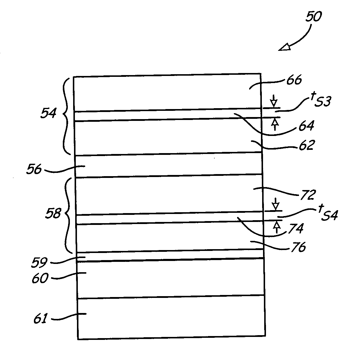
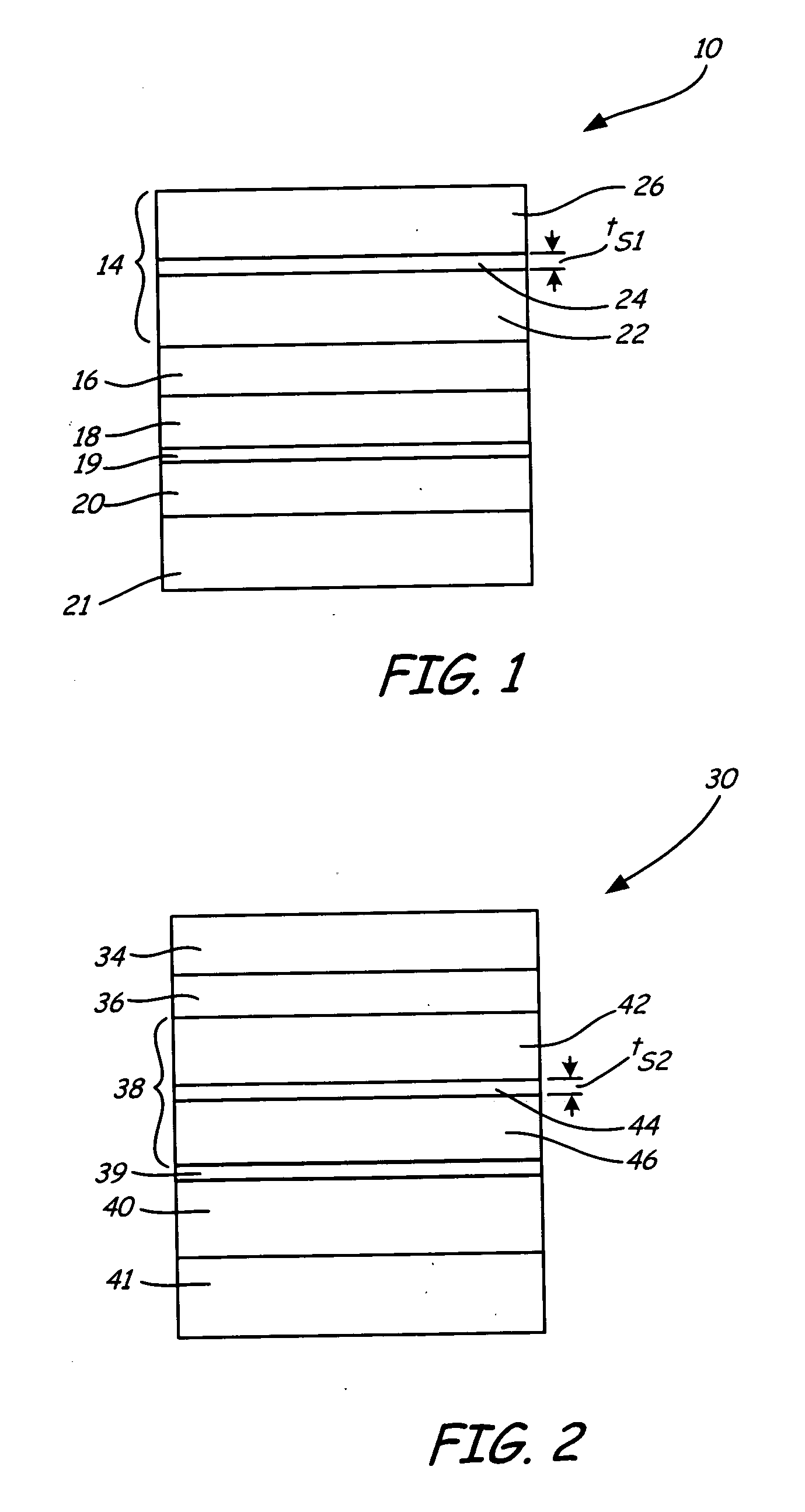
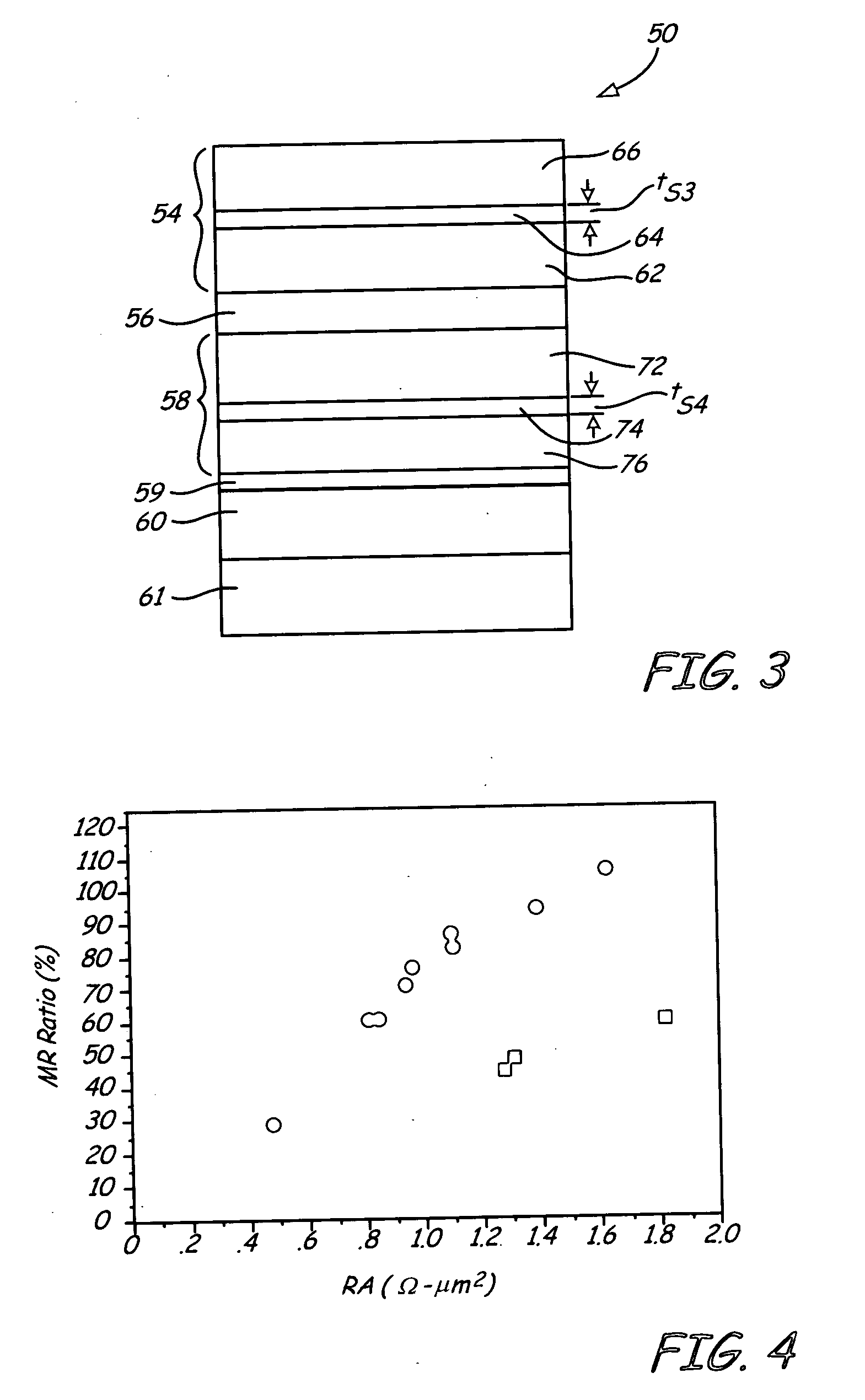
[0010]FIG. 1 is a layer diagram of a magnetic sensor 10, which includes free layer 14, barrier layer 16, reference layer 18, coupling layer 19, pinned layer 20, and pinning layer 21. Free layer 14 includes first ferromagnetic layer 22, sense enhancing layer 24, and second ferromagnetic layer 26. In one embodiment, magnetic sensor 10 is positioned between two electrodes or shields in a magnetic recording head. Magnetic sensor 10 may also include additional layers, such as a seed layer to promote growth of subsequent layers in magnetic sensor 10, and a cap layer to vary properties of magnetic sensor 10 such as resistance-area (RA) product and magnetoresistive (MR) ratio. It should be noted that the configuration of magnetic sensor 10 is merely illustrative, and other layer configurations for magnetic sensor 10 may be used in accordance with the present invention. For example, a second free layer may be substituted for reference layer 18 to form a tri-layer type magnetic sensor. In add...


PUM

PropertyMeasurementUnit
breakdown voltageaaaaaaaaaa
magnetostrictionaaaaaaaaaa
magnetoresistive ratioaaaaaaaaaa

Abstract

A magnetic sensor includes a sensor stack having a first magnetic portion, a second magnetic portion, and a barrier layer between the first magnetic portion and the second magnetic portion. At least one of the first magnetic portion and the second magnetic portion includes a multilayer structure having a first magnetic layer having a positive magnetostriction adjacent to the barrier layer, a second magnetic layer, and an intermediate layer between the first magnetic layer and the second magnetic layer. The magnetic sensor has an MR ratio of at least about 80% when the magnetic sensor has a resistance-area (RA) product of about 1.0 Ω·μm2.

Description

BACKGROUND OF THE INVENTION [0001] The present invention relates to magnetic sensors. More particularly, the present invention relates to a magnetic sensor including a tunneling barrier and a layer to improve the sensitivity of the sensor. [0002] In an electronic data storage and retrieval system, a magnetic recording head typically includes a reader portion having a sensor for retrieving magnetically encoded information stored on a magnetic disc. Magnetic flux from the surface of the disc causes rotation of the magnetization vector of a sensing layer or layers of the sensor, which in turn causes a change in the electrical properties of the sensor. The sensing layers are often called free layers, since the magnetization vectors of the sensing layers are free to rotate in response to external magnetic flux. The change in the electrical properties of the sensor may be detected by passing a current through the sensor and measuring a voltage across the sensor. Depending on the geometry ...

Claims


Application Information

Patent Timeline
Patent Type & Authority Applications(United States)
IPC IPC(8): G11B5/33G11B5/127
CPCB82Y10/00B82Y25/00G01R33/093G11B5/3906G11B5/3909Y10T428/1121H01F10/3272H01L43/08H01F10/3295Y10T428/1114H01F10/3254H10N50/10
Inventor GAO, ZHENGKARR, BRIAN W.XUE, SONGGRANSTROM, ERIC L.TRAN, KHUONG T.LI, YI X.
Owner SEAGATE TECH LLC
Why Eureka
Try Eureka