Optical System Having Aberrations for Transforming a Gaussian Laser-Beam Intensity Profile to a Quasi-Flat-Topped Intensity Profile in a Focal Region of the Optical System

a technology of optical system and intensity profile, applied in the field of laser beam shaping system, can solve the problems of inconvenient use of optical system homogenizers of microlens array beams, inability to produce comparable quality, and high production costs of all optical elements, and achieve the effect of reducing the diameter of laser beams

Active Publication Date: 2007-06-21
SOLTA MEDICAL
View PDF17 Cites 18 Cited by
  • Summary
  • Abstract
  • Description
  • Claims
  • Application Information

AI Technical Summary

Benefits of technology

[0009] There are several laser applications that can benefit from image intensity profiles that are quasi-flat-topped. By way of example, certain laser dermatological treatments have better tissue interactions and better thermal interactions when the incident intensity profile is of a flat-topped or quasi-flat-topped form than when the incident intensity profile is Gaussian. A flat-topped or quasi-flat-topped intensity profile reduces both charring of tissue at the center of the image and under-treatment at the periphery of the image. A large number of industrial laser welding, laser cutting, laser annealing, and related operations can also benefit from incident intensity profiles that are of a flat-topped or quasi-flat-topped form. Such image intensity profiles are useful in welding and other material processing operations because material at the center of the treated image does not become vaporized while material at the periphery remains in a solid state. Other aspects and potential applications of the present invention will be evident to one skilled in the art from the detailed description of the invention presented hereinbelow.

Problems solved by technology

All of these optical elements are usually more complex and expensive to produce, in comparable quality, than simple, spherical optical elements.
Microlens-array type beam homogenizers are not suitable for use in an optical system wherein a focused beam must be scanned as discussed above.

Method used


Image

  • Optical System Having Aberrations for Transforming a Gaussian Laser-Beam Intensity Profile to a Quasi-Flat-Topped Intensity Profile in a Focal Region of the Optical System
  • Optical System Having Aberrations for Transforming a Gaussian Laser-Beam Intensity Profile to a Quasi-Flat-Topped Intensity Profile in a Focal Region of the Optical System
  • Optical System Having Aberrations for Transforming a Gaussian Laser-Beam Intensity Profile to a Quasi-Flat-Topped Intensity Profile in a Focal Region of the Optical System

Examples


Embodiment Construction

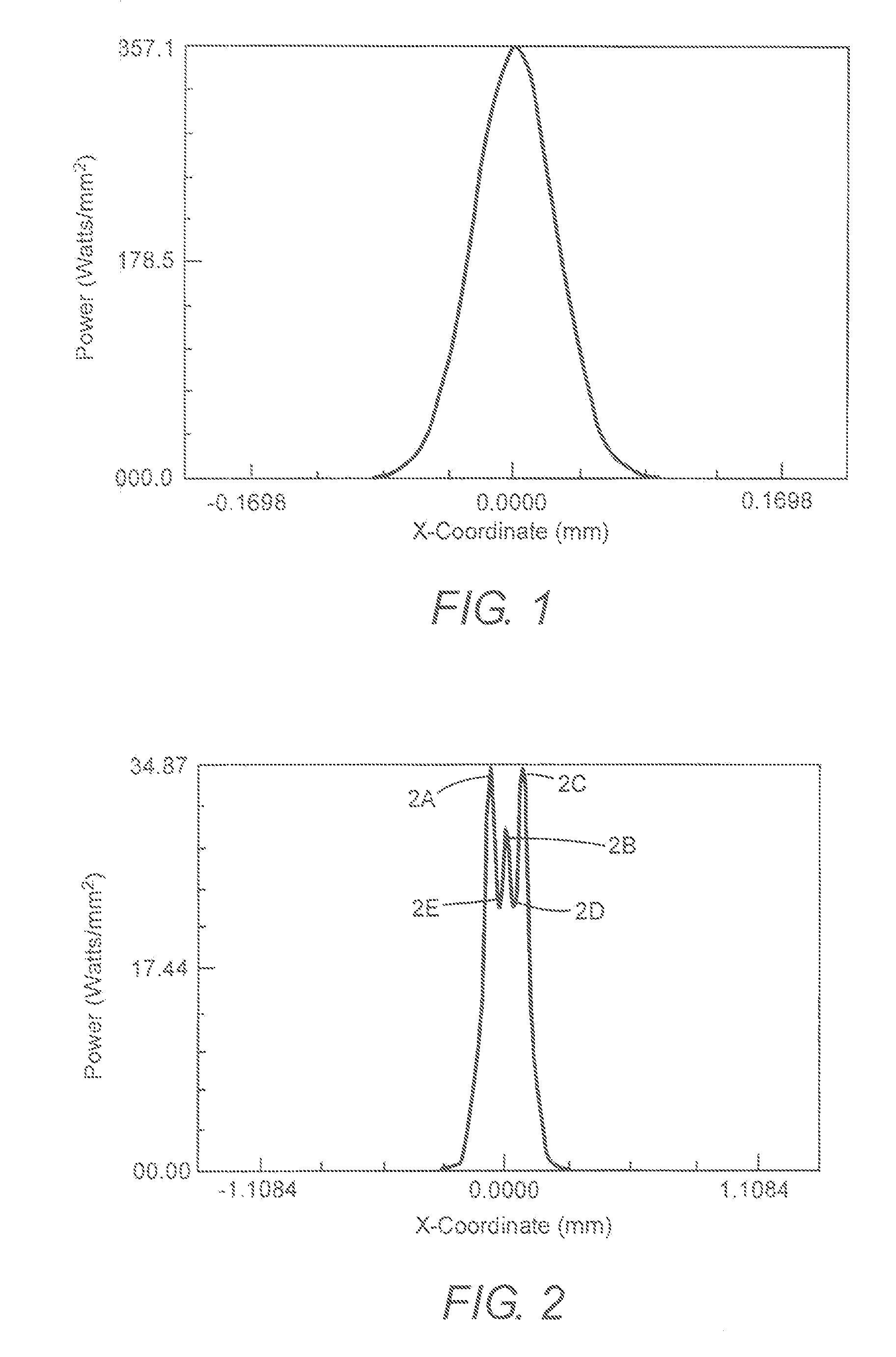
[0026] As noted above, a diffraction-limited optical system for projecting an image of a laser-beam Gaussian POP intensity profile (hereinafter, simply intensity profile) will produce an image that has a Gaussian radial intensity profile in a focal plane transverse to the optical axis of the optical system. This intensity profile will be the same at any transverse plane in a focal region extending from in front of, to behind the focal plane.

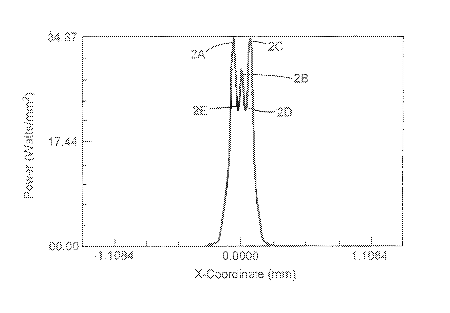
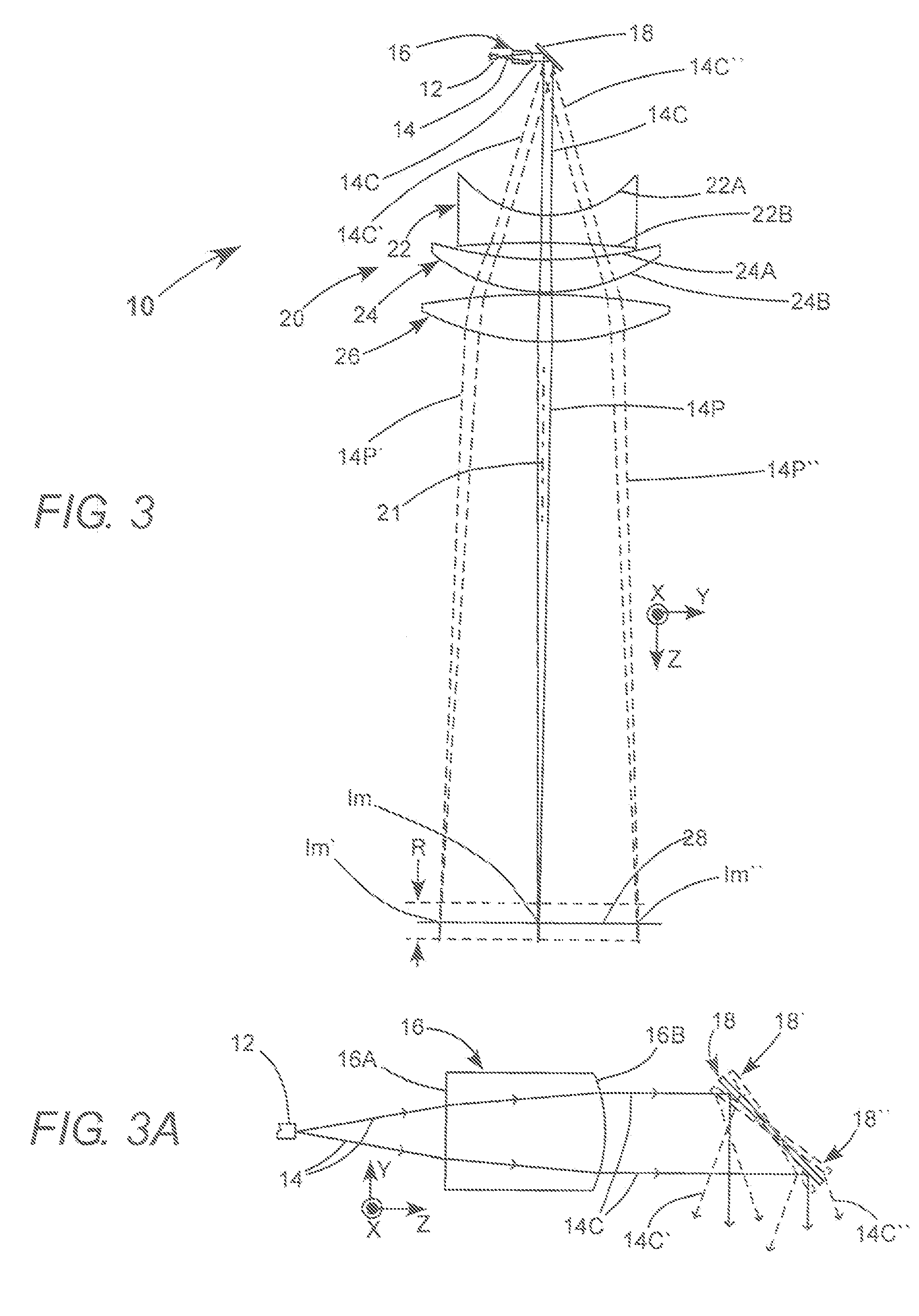
[0027] In embodiments of the present invention one or more aberrations, for example, third-order spherical aberration and defocus, are introduced into a Gaussian laser-beam before the beam is projected by a diffraction limited-imaging lens. These aberrations are used to make the image larger in diameter than would be the case for a comparable, entirely diffraction-limited system, to cause the image to have a lower peak intensity than a diffraction limited Gaussian image, and to have a quasi-flat-topped intensity profile. Embodiments of the prese...


PUM

PropertyMeasurementUnit
diameteraaaaaaaaaa
diameteraaaaaaaaaa
wavelengthaaaaaaaaaa

Abstract

An optical system is configured for projecting an image having a quasi-flat-topped intensity profile from a laser-beam having a Gaussian intensity profile. The optical system includes a diffraction limited lens for focusing the laser beam and one or more optical elements that introduce aberration into the beam before the beam is focused. The aberration introduced causes the Gaussian intensity profile to be changed to the quasi-flat-topped intensity profile at some position in a focal region of the diffraction-limited lens.

Description

CROSS-REFERENCE TO RELATED APPLICATION [0001] This application claims priority under 35 U.S.C. §119(e) to U.S. Provisional Patent Application Ser. No. 60 / 751,177, “Optical System Having Aberrations for Transforming a Gaussian Laser-Beam Intensity Profile to a Quasi-Flat-Topped Intensity Profile in a Focal Region of the Optical System,” filed Dec. 16, 2005, the subject matter of which is incorporated herein by reference in its entirety.TECHNICAL FIELD OF THE INVENTION [0002] The present invention relates in general to laser-beam shaping systems. The invention relates in particular to optical systems for projecting a laser-beam, initially having a Gaussian intensity profile, into an image plane such that, in the image plane, the intensity profile in the beam is quasi-flat-topped. DISCUSSION OF BACKGROUND ART [0003] Many types of laser can be configured to deliver a beam in a single longitudinal mode with maximum beam quality. Beam quality is usually defined by a term M2. The beam qual...

Claims


Application Information

Patent Timeline
Patent Type & Authority Applications(United States)
IPC IPC(8): G11B7/135G11B7/00
CPCG02B27/0927G02B27/0955
Inventor FRANGINEAS, GEORGE
Owner SOLTA MEDICAL
Why Eureka
Try Eureka