Method and apparatus for characterizing a glass ribbon

a technology of glass ribbons and glasses, applied in the field of glasses forming methods, can solve the problems of reducing the quality of glass sheets, and reducing the residual stress and/or shap

Inactive Publication Date: 2007-06-21
CORNING INC
View PDF24 Cites 66 Cited by
  • Summary
  • Abstract
  • Description
  • Claims
  • Application Information

AI Technical Summary

Benefits of technology

[0012] Embodiments of the present invention provide a method and apparatus for making a glass sheet. More particularly, the method and apparatus may be used to characterize a ribbon of glass formed in a downdraw glass making process by measuring certain attributes of the ribbon. The data developed by using the present invention can be used to control the glass making process, thereby improving the quality of resultant glass sheets cut from the ribbon by reducing the residual stress and / or shape of the ribbon.
[0014] Advantageously, the method can facilitate performing attribute measurements across substantially the entire width (from the first side edge to the second side edge) of the glass ribbon, or a portion thereof, with a high degree of spatial resolution.

Problems solved by technology

Although the amount of shape change is typically quite small, in view of the pixel structures used in modern displays, the distortion resulting from cutting can be large enough to lead to substantial numbers of defective (rejected) displays.
Accordingly, the distortion problem is of substantial concern to display manufacturers and specifications regarding allowable distortion as a result of cutting can be as low as 2 microns or less.
These temperature variations can result in setting up stress in the sheet as it cools from a viscous liquid to an elastic solid.
In addition, the scoring process, or other downstream processing, may create movement in the ribbon which is transferred upward to the visco-elastic region of the ribbon, where such movement may result in the freezing-in of residual stress or shape in the glass which may contribute to deformities in the finished product.
This can be a source of change of the ribbon shape in the elastic region which propagates to the visco-elastic region and thus can result in frozen-in stress or shape.
Unfortunately, the need to fully enclose the forming region of the draw machine makes measurements of the glass ribbon difficult at best.
Unfortunately, the need to minimize the number of penetrations into the enclosure likewise limits access to the ribbon for the pupose of making attribute measurements: attribute measurements can be taken only spottily, limiting the ability to acquire a full picture of the attributes distribution along a width or length of the ribbon.
They are therefore incapable of accurately discerning temperature gradients which may be hundreds of degrees across relatively short distances, on the order of millimeters or centimeters.
Also, unlike other glass forming processes, notably the so-called float process wherein a glass sheet is formed by floating molten glass on a reservoir of molten metal, in a downdraw glass forming process, such as the fusion process, the glass ribbon is suspended in air and very susceptible to deformation.
Contact-type attribute measurements are also unsuitable, particularly for applications where the end use of the glass sheet requires a high degree of optical clarity, such as display applications, as contact with the surface of the glass would destroy the pristine nature of the glass.
Finally, glass for display applications is exceptionally thin, typically less than about 1 mm, and more typically less than 0.7 mm, and is therefore very susceptible to mechanically and thermally-induced deformation.

Method used


Image

  • Method and apparatus for characterizing a glass ribbon
  • Method and apparatus for characterizing a glass ribbon
  • Method and apparatus for characterizing a glass ribbon

Examples


Embodiment Construction

[0028] In the following detailed description, for purposes of explanation and not limitation, example embodiments disclosing specific details are set forth to provide a thorough understanding of the present invention. However, it will be apparent to one having ordinary skill in the art, having had the benefit of the present disclosure, that the present invention may be practiced in other embodiments that depart from the specific details disclosed herein. Moreover, descriptions of well-known devices, methods and materials may be omitted so as not to obscure the description of the present invention. Finally, wherever applicable, like reference numerals refer to like elements.

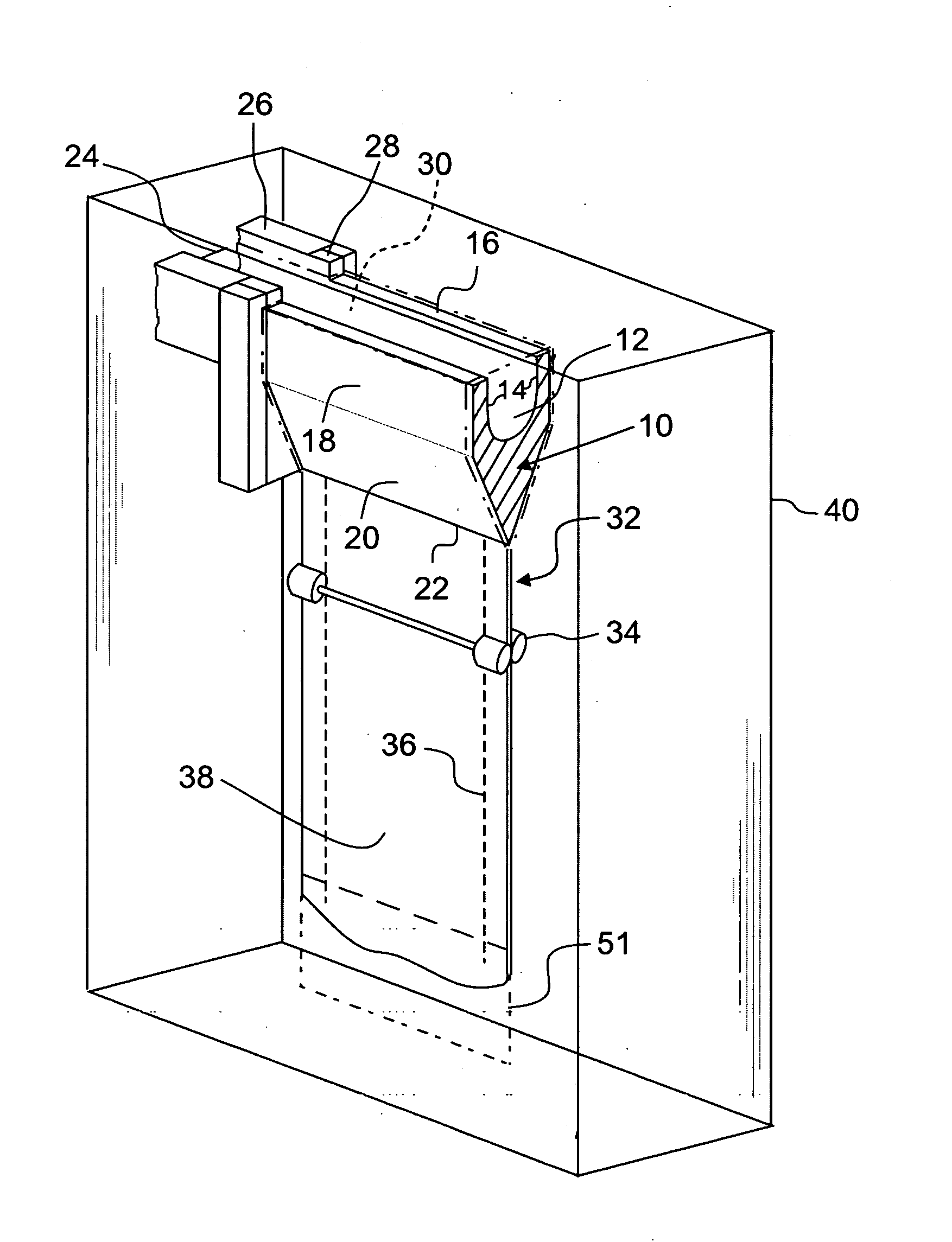
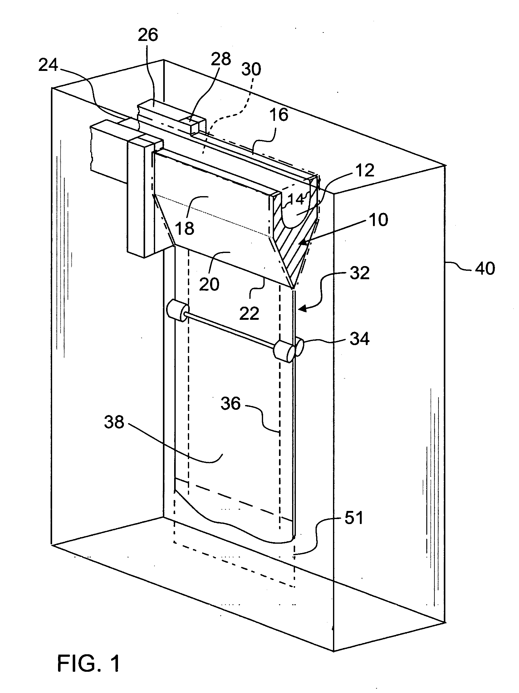
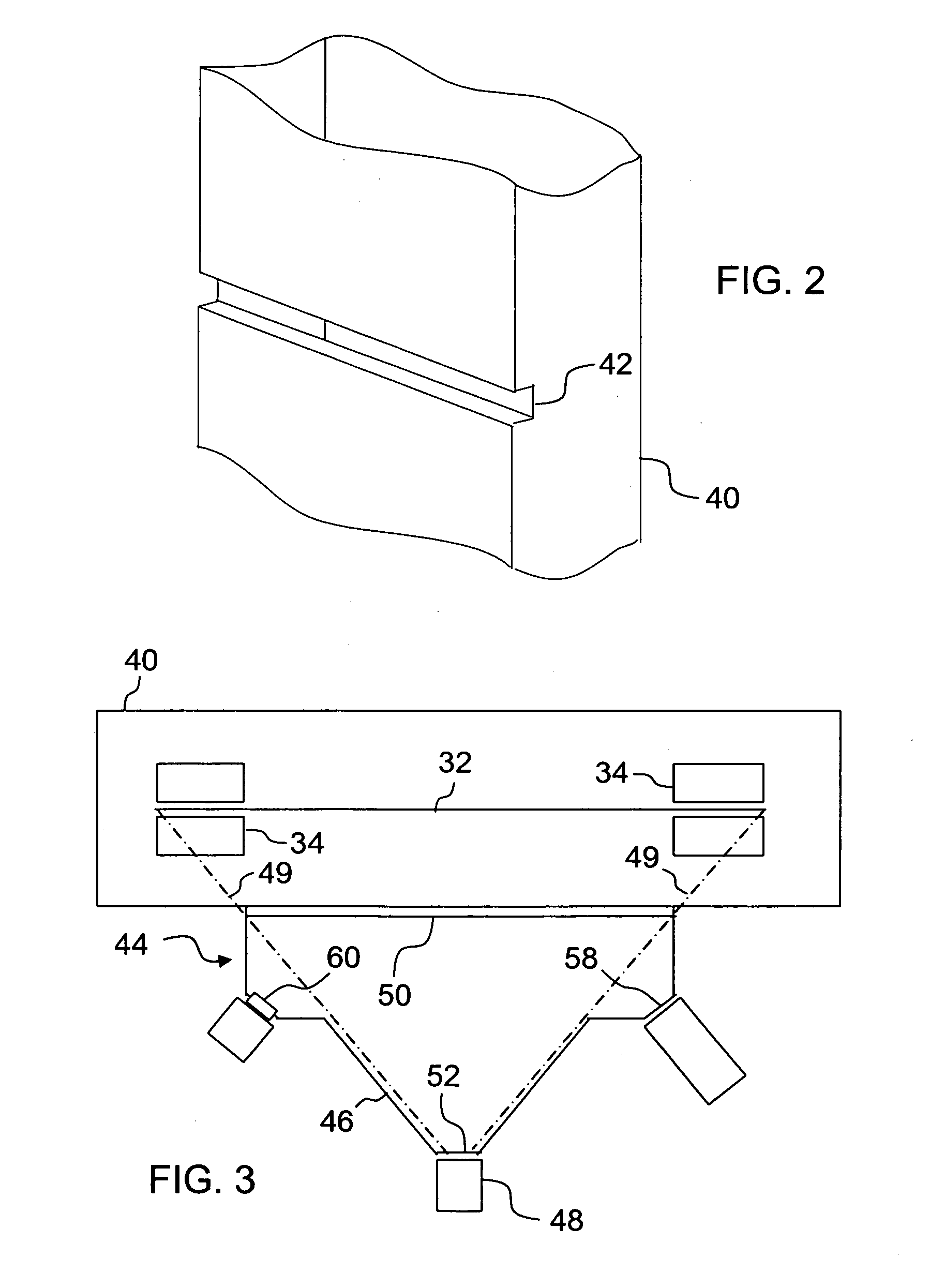
[0029] Embodiments of the present invention relate to a method and an apparatus for measuring an attribute or characteristics of a sheet, or ribbon, of glass formed by a downdraw process. Such attributes include, but are not limited to, temperature. Other desirable attributes may include displacement of the ribbo...


PUM

PropertyMeasurementUnit
widthaaaaaaaaaa
temperaturesaaaaaaaaaa
wavelengthaaaaaaaaaa

Abstract

A method and apparatus for measuring the temperature and / or displacement of a glass ribbon formed in a downdraw glass forming process, and measured across width of the ribbon. Temperature and displacement measurements may advantageously be performed simultaneously with a high degree of spatial resolution by a measurement assembly which does not contact the glass ribbon. Temperature measurements may be performed across substantially the entire width of the ribbon. Data developed by the measurement assembly may be used in an automated feedback loop to control the glass ribbon forming conditions.

Description

BACKGROUND OF THE INVENTION [0001] 1. Field of the Invention [0002] This invention is directed to a method of forming glasses, particularly those formed in a fusion downdraw glass making process. More particularly, the apparatus and method according to the present invention provide for the characterization of a glass ribbon wherein an attribute of the ribbon is acquired with a high spatial resolution. [0003] 2. Technical Background [0004] Display devices are used in a variety of applications. For example, thin film transistor liquid crystal displays (TFT-LCDs) are used in notebook computers, flat panel desktop monitors, LCD televisions, and Internet and communication devices, to name only a few. [0005] Many display devices, such as TFT-LCD panels and organic light-emitting diode (OLED) panels, are made directly on flat glass sheets (glass substrates). To increase production rates and reduce costs, a typical panel manufacturing process simultaneously produces multiple panels on a sin...

Claims


Application Information

Patent Timeline
Patent Type & Authority Applications(United States)
IPC IPC(8): G01K1/00G01K13/12C03B18/18
CPCC03B17/064G01J2005/0081G01J2005/0077Y02P40/57G01J5/48G01K13/12G01K1/00C03B13/00
Inventor HOUSE, KEITH LEONARDKLINGENSMITH, LEWIS KIRKNISHIMOTO, MICHAEL YOSHIYAWESOLOWSKI, PIOTR JANUSZ
Owner CORNING INC
Why Eureka
Try Eureka