Automated fraction collection system

a fraction collection and fraction collection technology, applied in the field of fraction collection system, can solve the problems of time-consuming and complicated methods

Active Publication Date: 2007-06-21
ALFA WASSERMANN INC
View PDF14 Cites 8 Cited by
  • Summary
  • Abstract
  • Description
  • Claims
  • Application Information

AI Technical Summary

Problems solved by technology

Such methodologies are complicated and time consuming particularly when minute fractions of large samples are being analyzed.

Method used


Image

  • Automated fraction collection system
  • Automated fraction collection system
  • Automated fraction collection system

Examples


Embodiment Construction

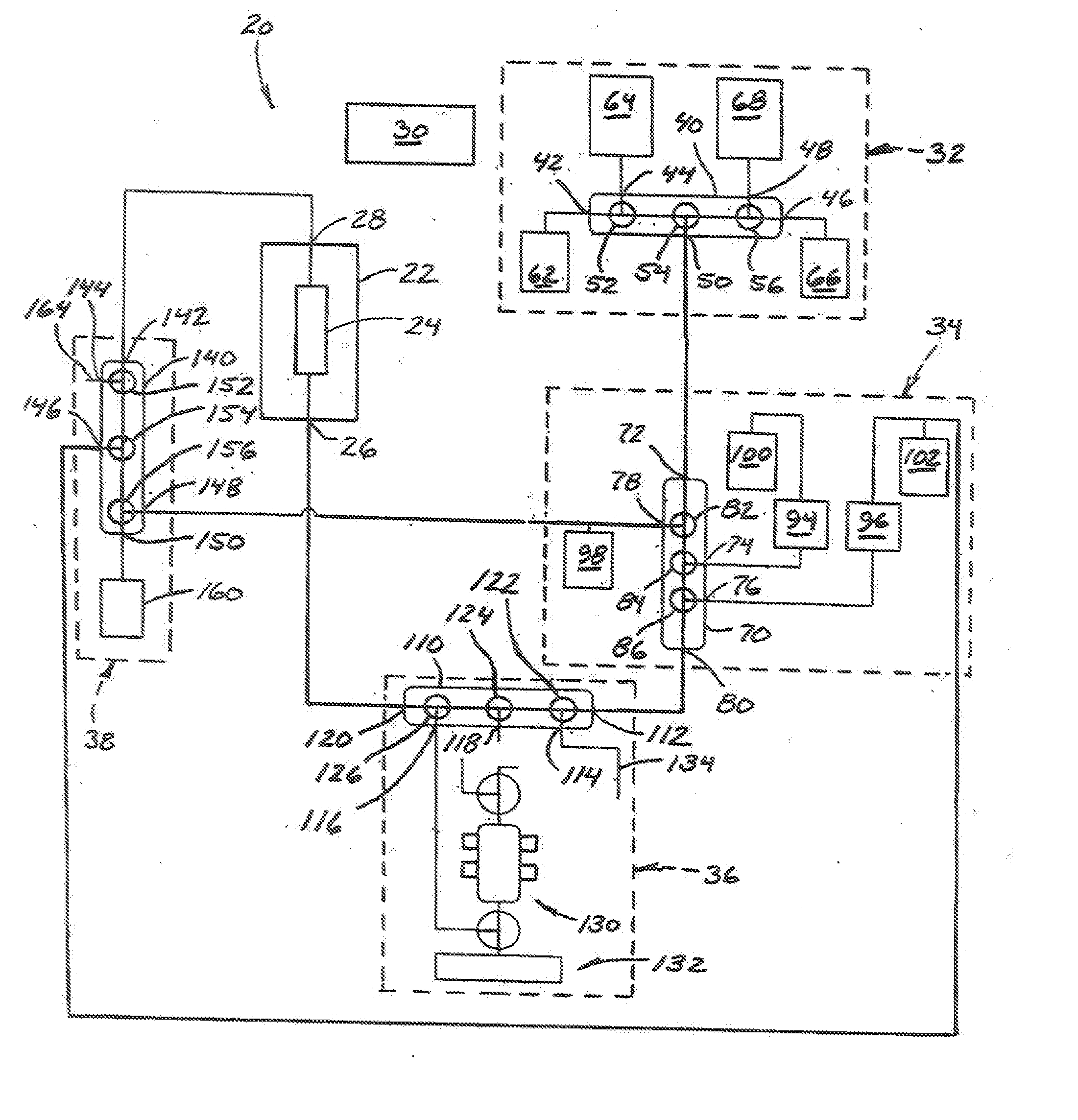
[0015] Referring now to the drawings and in particular to FIG. 1, a system of the present invention is designated in its entirety by the reference numeral 20. The system 20 includes an ultracentrifuge 22 having a cylindrical rotor 24 that spins about a vertically-oriented axis at high speeds (e.g., speeds as high as 35,000 revolutions per minute (rpm) or more) to separate particles contained in solution in the rotor according to their buoyant density. The rotor 24 has a sample port 26 at its lower end through which samples are introduced and withdrawn. An overflow port 28 is provided at an upper end of the rotor 24. An electric motor (not shown) controlled by a processor 30 is used to spin the rotor 24. Although other processors may be used without departing from the scope of the present invention, in one embodiment the processor is a CFP-2020 compact field point network module available from National Instruments Corporation of Austin, Tex. As will be appreciated by those skilled in...


PUM


Abstract

A system for separating a sample and collecting the separated sample. The system includes an ultracentrifuge having a cylindrical rotor. The system includes a gradient delivery assembly for delivering a gradient solution to the ultracentrifuge rotor, and a sample delivery assembly for delivering the solution containing the sample to the ultracentrifuge rotor. he system includes a fraction collection assembly for collecting discrete volumes of the separated sample. The system includes a processor for controlling operation of the ultracentrifuge, as well as the gradient delivery assembly, the sample delivery assembly, and / or the fraction collection assembly.

Description

BACKGROUND OF THE INVENTION [0001] The present invention relates generally to a fraction collection system, and more particularly to an automated system permitting separation, enrichment and fractionation of sub-cellular particles. [0002] Characterization of biological materials, such as biological molecules and organelles, has become increasingly important. Precise characterization of these materials can lead to novel drug therapies for treating disease, as well as to a greater understanding of the mechanisms underlying many diseases. Many biological materials exhibit a buoyant density that can be used to distinguish them from other materials. Such materials can be separated using density gradients and procedures such as differential centrifugation. For example, lipoproteins are composed of varying amounts of proteins and lipids. They differ not only by size and electrophoretic mobility, but also by buoyant density. Thus, in addition to other techniques available for separating, id...

Claims


Application Information

Patent Timeline
Patent Type & Authority Applications(United States)
IPC IPC(8): B04B11/04B04B13/00
CPCB04B11/04B04B13/00G01F23/2921G01N1/18G01N1/40G01F11/284G01F11/44G01N2001/4083
Inventor MARSH, BLAINE J.
Owner ALFA WASSERMANN INC
Why Eureka
Try Eureka