Design and assembly of fenestrated stent grafts

a stent and aortic aorta technology, applied in the field of preoperative sizing and assembly of stent grafts, can solve the problems of insufficient apposition between the stent-graft and the aorta to achieve a reliable seal, slow development of endovascular methods for thoracic abdominal and pararenal aortic repair, and high mortality and morbidity rates, so as to reduce the overall diameter of the sten

Active Publication Date: 2007-06-21
COOK MEDICAL TECH LLC
View PDF8 Cites 121 Cited by
  • Summary
  • Abstract
  • Description
  • Claims
  • Application Information

AI Technical Summary

Benefits of technology

[0032] d) drawing the ends of the thread together and tying ends of the thread, whereby the selected distance is reduced thereby reducing the overall diameter of the stent graft.
[0036] g) drawing the ends of the second thread together and tying ends of the thread, whereby the selected distance is reduced thereby reducing the overall diameter of the stent graft.

Problems solved by technology

Despite advances in surgical technique and perioperative care, the mortality and morbidity rates remain high, especially in patients who are old, sick, or have already undergone open surgical repair of an adjacent segment of the aorta.
In such cases, an endovascular alternative would be welcome, yet endovascular methods of thoracoabdominal and pararenal aortic repair have been slow to develop.
The challenge has been to exclude the aortic aneurysm while maintaining flow to its visceral branches.
Under these circumstances, there is insufficient apposition between the stent-graft and the aorta to achieve a reliable seal.
Positioning is further complicated because the diameter of a stent graft is deliberately made larger than the diameter into which it is to be placed to allow for accurate sealing against the vessel wall, possible errors in sizing and subsequent relaxation of the vessel wall.
A further problem exists that upon deployment and release of the stent graft it is desirable that the graft open up from its confined delivery state to a released position under the influence of self expanding stents with the fenestrations aligned with the renal arteries, for instance.

Method used


Image

  • Design and assembly of fenestrated stent grafts
  • Design and assembly of fenestrated stent grafts
  • Design and assembly of fenestrated stent grafts

Examples


Embodiment Construction

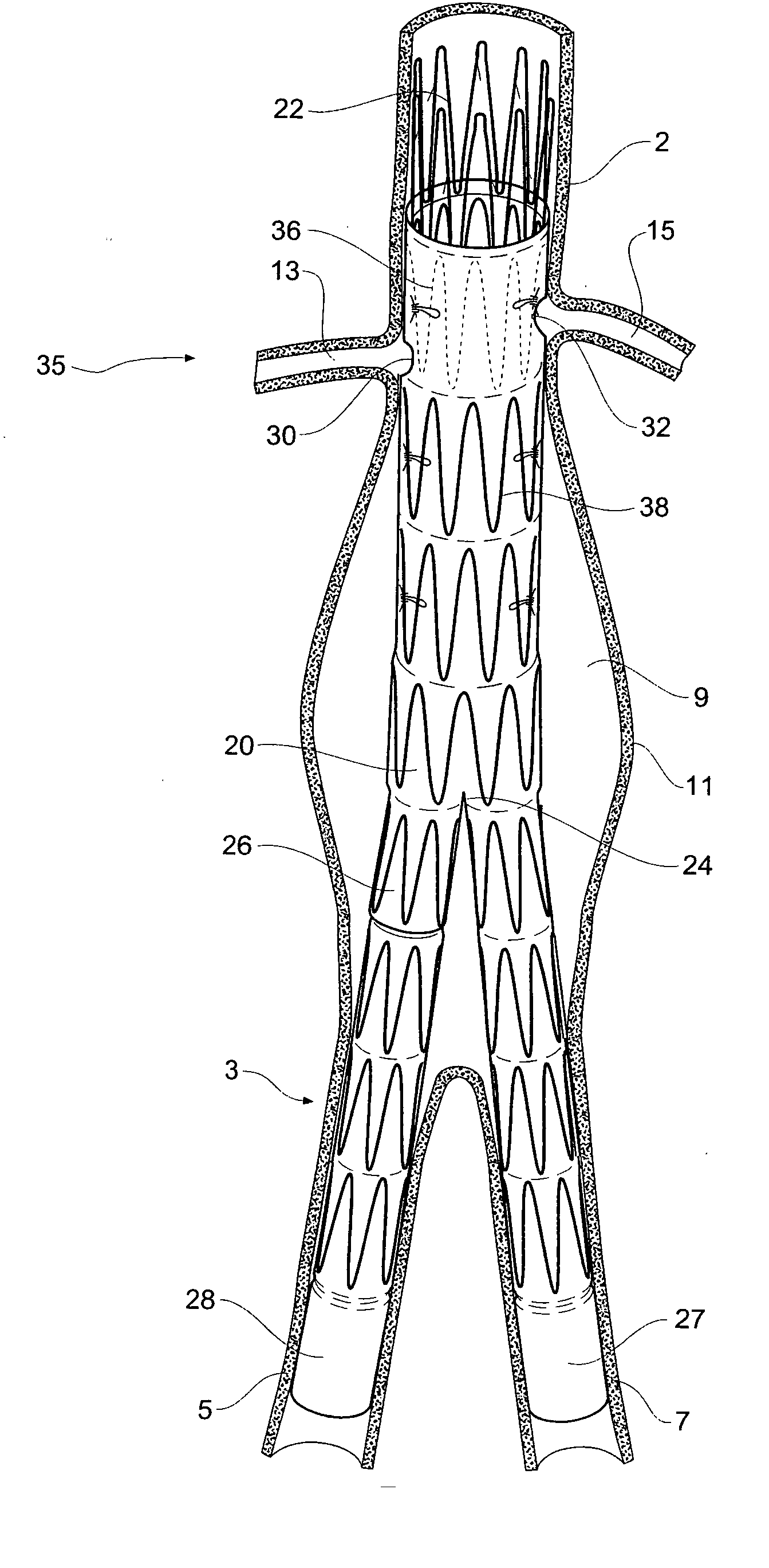
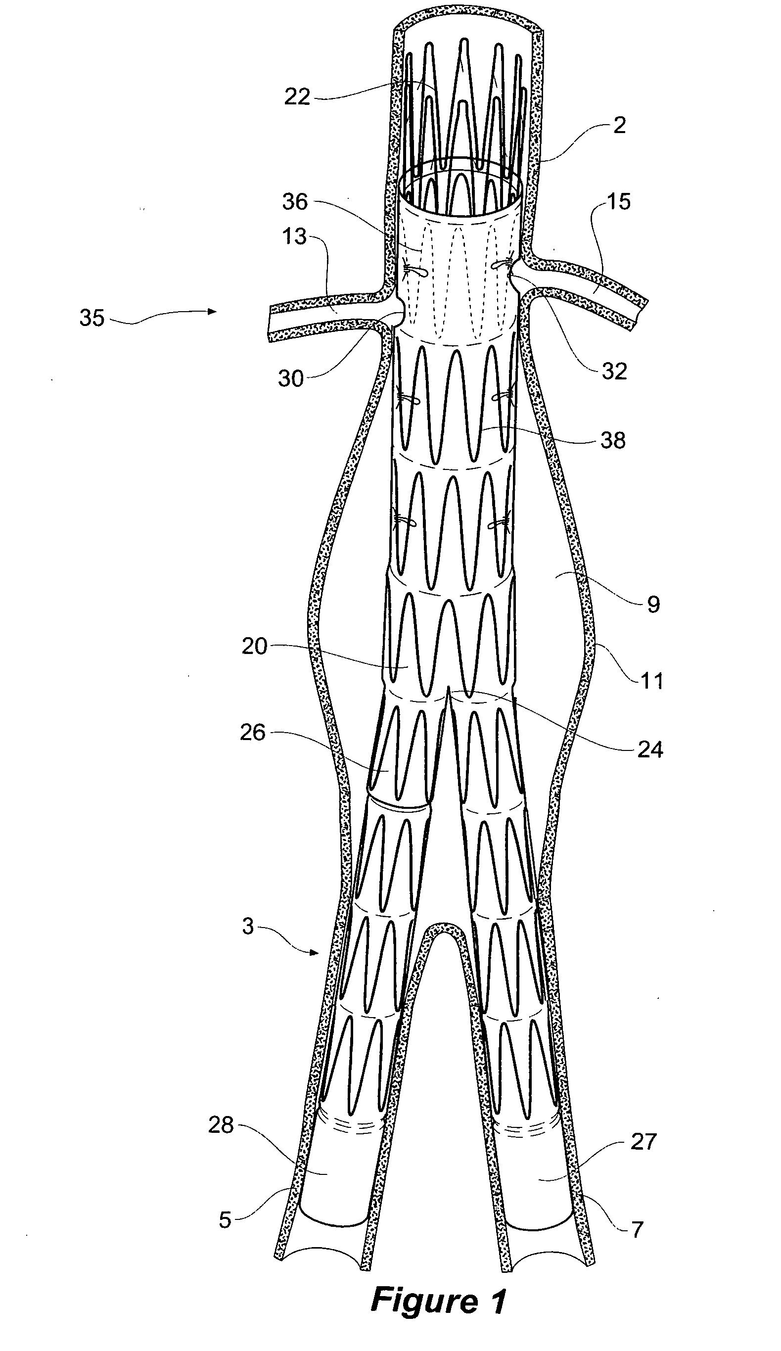
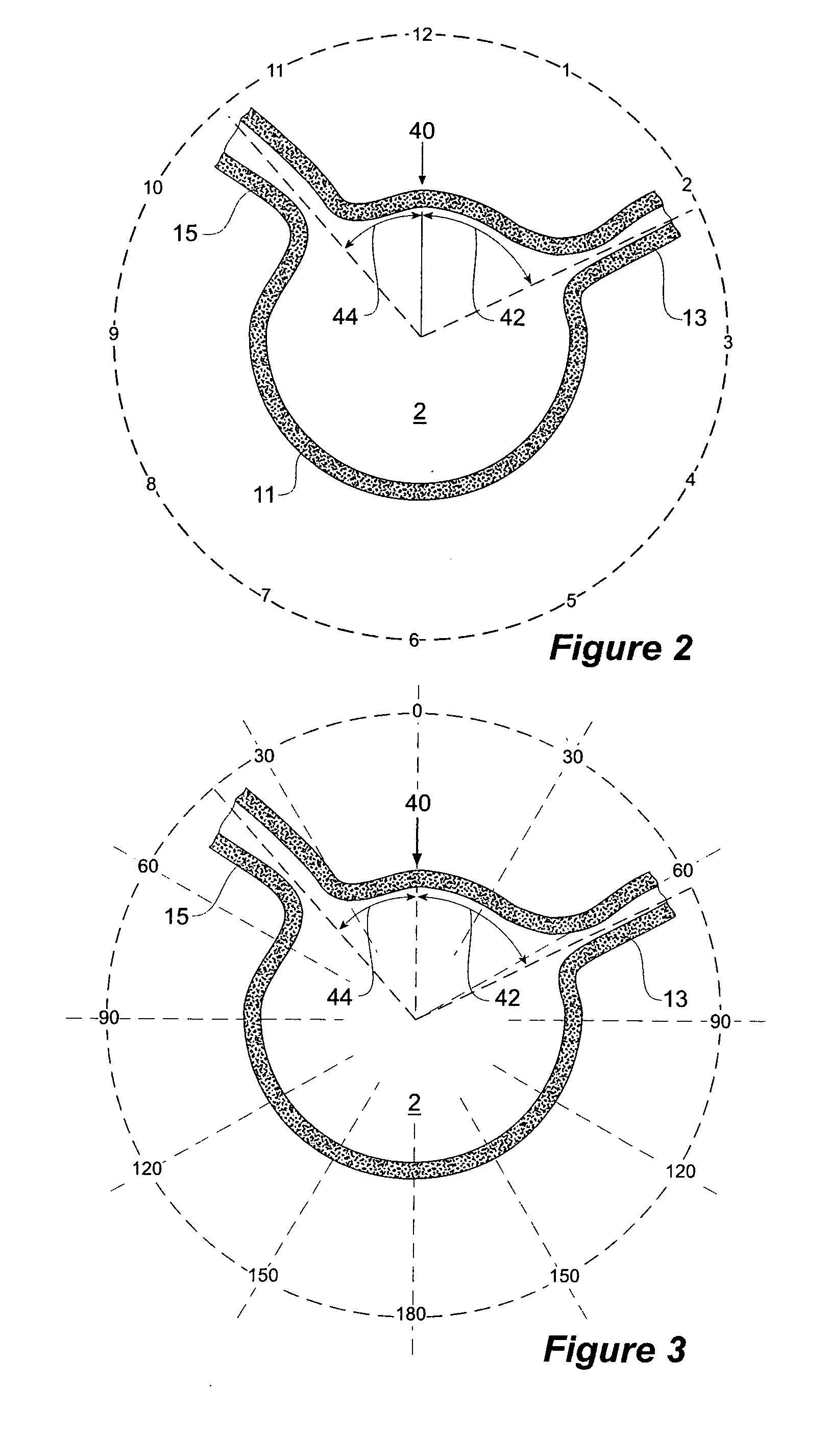
[0057] Now looking more closely at the drawings and in particular FIG. 1 it can be seen that there is schematically shown an aorta 2 extending down to an aortic bifurcation at 3 and into two iliac arteries 5 and 7. An aneurysm 9 defined by a bulge in the aorta wall 11 extends from near to the aortic bifurcation 3 nearly to the renal arteries 13 and 15. There is insufficient non-aneurysed length of the aorta distally of the renal arteries and hence to place a stent graft to bypass the aneurysm it is necessary to place some of the stent graft proximally of the renal arteries.

[0058] This embodiment of the invention is discussed in relation to a bifurcated stent graft having a longer leg for extending into one iliac artery and a shorter leg into which a leg extension may be deployed for the contralateral iliac artery but the invention is not so limited and may also be used for a composite stent graft in which the fenestrations are in a proximal tubular portion of the composite stent gr...


PUM


Abstract

A method of sizing of a stent graft ( 20 ) including placement of fenestrations ( 30, 32 ) to ensure access to side branch vessels ( 13, 15 ) through the fenestrations when the stent graft is introduced into a body vessel and an assembly method for a stent graft including temporary diameter reduction arrangements to enable partial release of a stent graft to assist with positioning of fenestrations with respect to side branch vessels. The method includes spacing the fenestrations to be the same circumferential distance as the side branch vessels irrespective of the diameter of the stent graft.

Description

CROSS-REFERENCE TO RELATED APPLICATIONS [0001] This application claims priority of provisional application Ser. No. 60 / 709,411, filed Aug. 18, 2005.TECHNICAL FIELD [0002] This invention relates to pre-operative sizing and assembly of a stent graft for deployment and more particularly to a stent graft with fenestrations. BACKGROUND OF THE INVENTION [0003] This invention will be particularly discussed in relation to stent grafts for placement into the thoracoabdominal aorta for the treatment of aneurysms and more specifically in relation to juxtarenal placement. The invention, however, is not so restricted and may be applied to stent grafts for placement in any lumen of the human or animal body. [0004] The segment of aorta between the celiac and renal arteries is the best endowed with adventitial elastin, the most stable, and the last to dilate. Aneurysms of this area are associated with aneurysms of less stable areas in the descending thoracic aorta, infrarenal aorta, or both. Surgic...

Claims


Application Information

Patent Timeline
Patent Type & Authority Applications(United States)
IPC IPC(8): A61F2/90A61F2/06
CPCA61F2/07A61F2002/061A61F2002/065A61F2002/075A61F2002/9505A61F2230/0067A61F2250/0039A61F2/89A61F2230/005A61F2230/0054A61F2002/9511
Inventor ANDERSON, JOHN LENNONHARTLEY, DAVID ERNESTLAWRENCE-BROWN, MICHAEL
Owner COOK MEDICAL TECH LLC
Why Eureka
Try Eureka