Adjustable prosthetic valve implant

a prosthetic valve and implant technology, applied in the field of adjustable prosthetic valve implants, can solve the problems of ineffective closure of valve leaflets, insufficient valve leaflets, and inability to adjust the size of the implant,

Inactive Publication Date: 2007-06-21
MICARDIA CORP
View PDF8 Cites 514 Cited by
  • Summary
  • Abstract
  • Description
  • Claims
  • Application Information

AI Technical Summary

Benefits of technology

[0019] For purposes of summarizing the invention, certain aspects, advantages, and novel features of the invention have been described herein. It is to be understood that not necessarily all such advantages may be achieved in accordance with any particular embodiment of the invention. Thus, the invention may be embodied or carried out in a manner that achieves or optimizes one advantage or group of advantages as taught herein without necessarily achieving other advantages as may be taught or suggested herein.

Problems solved by technology

If the valves of the heart do not function properly, due either to disease or congenital defects, the circulation of the blood may be compromised.
Diseased heart valves may be stenotic, wherein the valve does not open sufficiently to allow adequate forward flow of blood through the valve, and / or incompetent, wherein the valve does not close completely.
Incompetent heart valves cause regurgitation or excessive backward flow of blood through the valve when the valve is closed.
When a heart valve annulus dilates, the valve leaflet geometry deforms and causes ineffective closure of the valve leaflets.
The ineffective closure of the valve can cause regurgitation of the blood, accumulation of blood in the heart, and other problems.
Although surgical valve replacement concerns about 200,000 patients worldwide every year, it is estimated that up to two thirds of these patients do not receive surgery due to either excessive risk factors and comorbidities or patient refusal due to fear of lifestyle changes following heavy surgery in elderly patients.
Although a number of minimally invasive techniques for replacing heart valves do exist, they are often problematic.
For example, with many minimally invasive valve replacements, paravalvular leaks can occur, with moderate to severe leakage occurring in 25% of cases.
These calcified lesions are extremely difficult to remove without fragmentation and without leaving some pieces of calcium, which may migrate and embolize.
Accurate and secure deployment of the valve prostheses will remain a significant issue for these endovascular procedures.
The resultant paravalvular leak is somewhat unpredictable at the time of the implantation.

Method used


Image

  • Adjustable prosthetic valve implant
  • Adjustable prosthetic valve implant
  • Adjustable prosthetic valve implant

Examples


embodiment 100

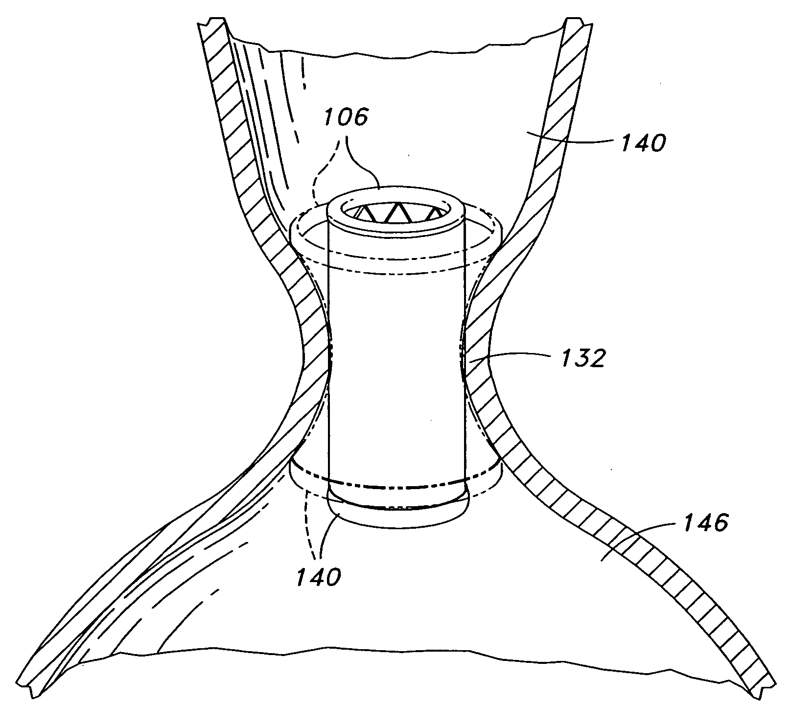
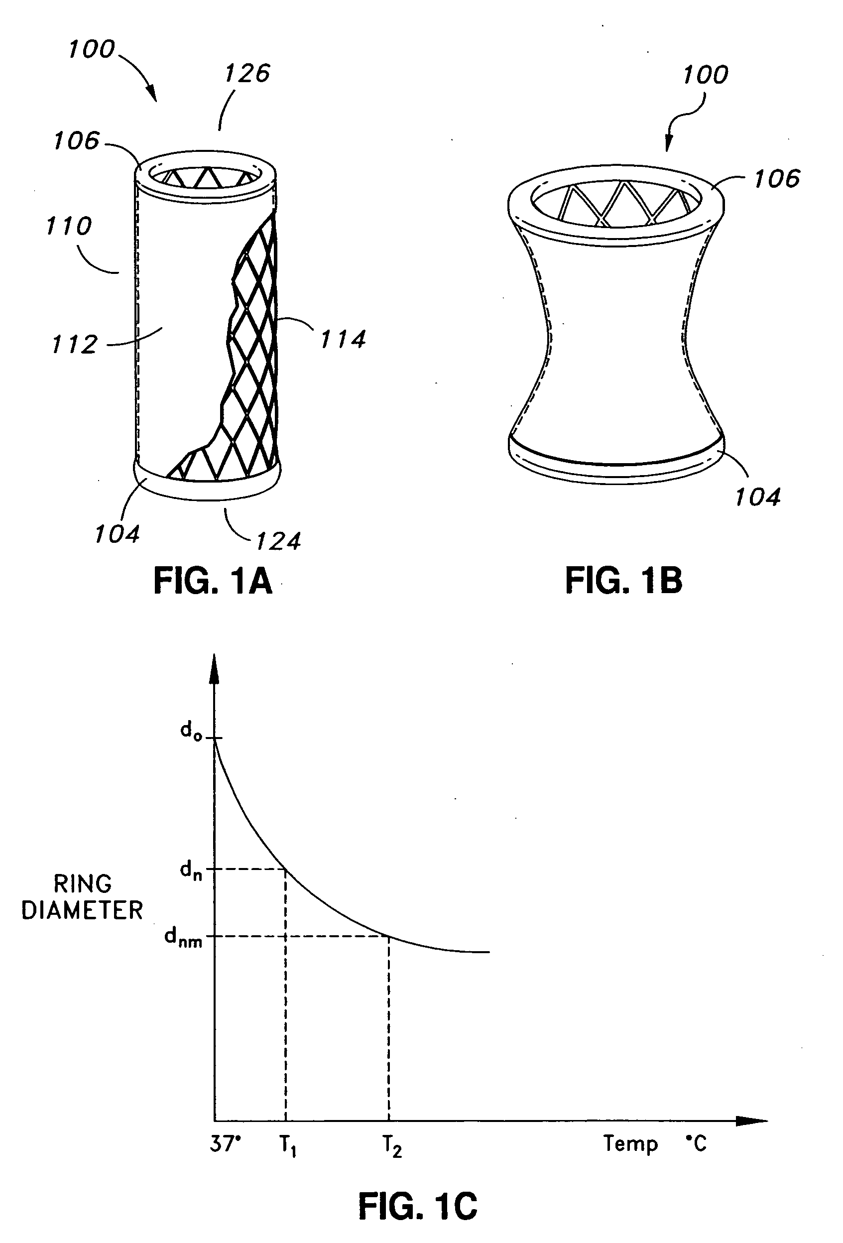
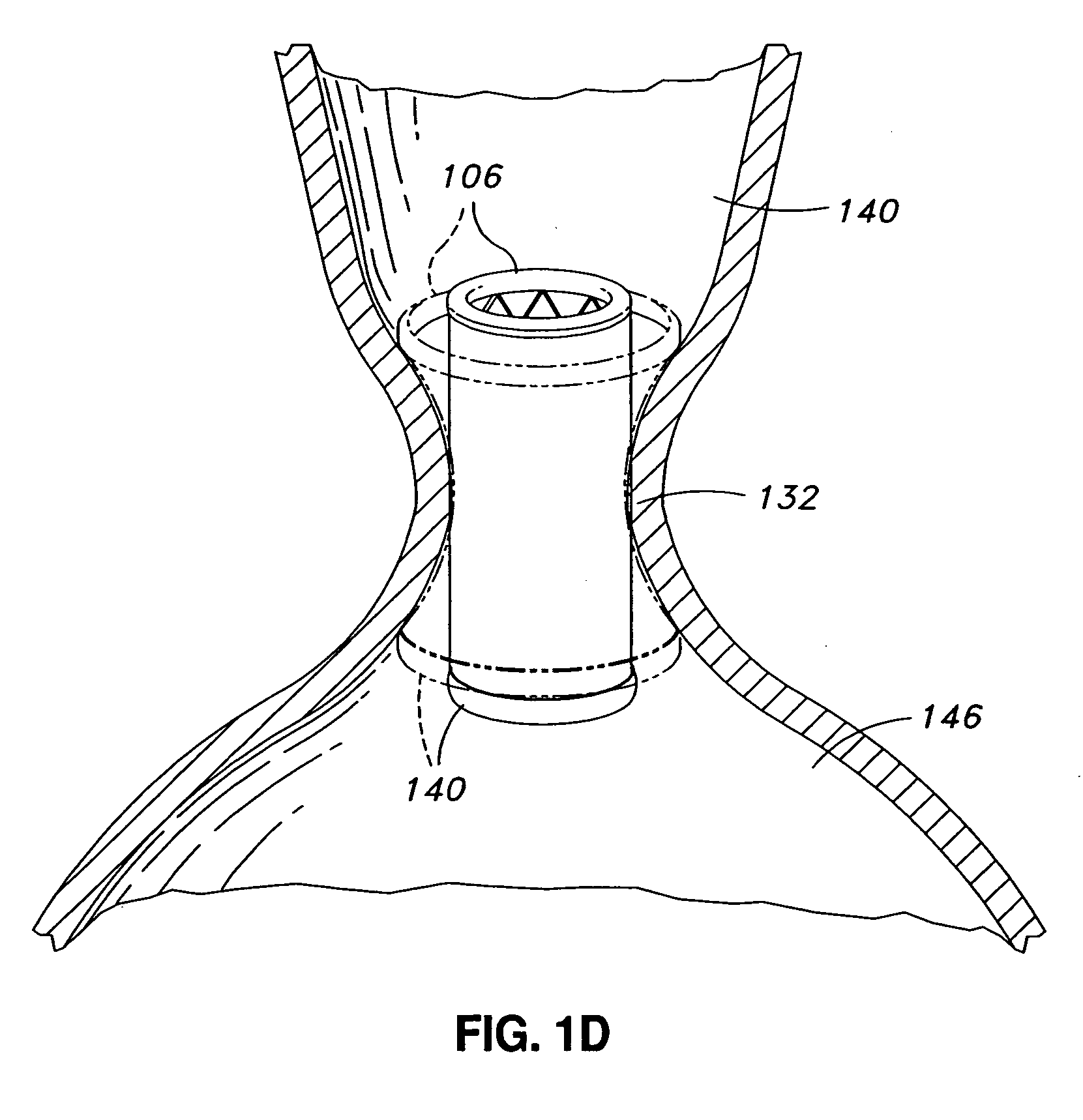
[0107] The illustrated embodiment 100 comprises a plurality of adjustable elements which, in the illustrated embodiment, are adjustable rings 104 and 106. Those skilled in the art will understand that the following description of the adjustable rings 104 and 106 is equally applicable to other types of adjustable elements. As used, the term “ring” broadly refers to shapes that are closed or open. In the illustrated embodiment, the adjustable rings 104 and 106 are substantially circular, closed rings.

[0108] In certain embodiments, the prosthetic valve implant may comprise additional adjustable rings. For example, in certain embodiments, the prosthetic valve implant may comprise an adjustable ring in a location substantially equidistant from the rings 106 and 104 located at the proximal and distal ends 126 and 124 of the implant 100, respectively.

[0109] In the illustrated embodiment, adjustable rings 106 and 104 are located at the proximal 126 and distal ends 124 of the implant 100, r...

embodiment 800

[0150]FIG. 9 illustrates a side view of an embodiment of a prosthetic valve implant 900 according to certain embodiments. The implant 900 is illustrated in an unadjusted configuration in solid lines, and in an adjusted configuration in phantom. The central region 902 of the implant 900 comprises an inward depression 908 on one side, similar to the embodiment 800 illustrated in FIG. 8. The construction and materials for this embodiment are substantially similar as described above for the embodiment illustrated in FIG. 6. Upon adjustment of the prosthetic valve implant 900, the depression 908 increases in depth and width. The depression 908 in the side of the implant 900 in its adjusted shape has become substantially larger than in the unadjusted configuration. In certain embodiments, the upstream end 906 portion and the downstream end 904 portion remain unaffected by the adjustment.

[0151] Although the embodiments of the adjustable prosthetic valve implant described so far are substan...


PUM


Abstract

A prosthetic implant for treating a diseased aortic valve is described. The prosthetic implant includes a substantially tubular body configured to be positioned in an aorta of a patient, at or near the patient's aortic valve. The body includes a lumen extending through the body from a proximal end to a distal end of the body; and an adjustable frame surrounding the lumen. The prosthetic implant further includes at least one adjustable element located in or on the body and extending at least partially around a circumference of the lumen. The at least one adjustable element includes a shape memory material and is transformable, in response to application of an activation energy, from a first configuration to a second configuration, wherein the first configuration and second configuration differ in a size of at least one dimension of the at least one adjustable element. The at least one adjustable element may engage at least one of a root of the aorta, an annulus of the aortic valve, and the patient's left ventricle, when the at least one adjustable element is in the second configuration.

Description

CROSS REFERENCE TO RELATED APPLICATIONS [0001] This application claims the benefit under 35 U.S.C. § 119(e) of U.S. Provisional Patent Application No. 60 / 751,036, filed on Dec. 16, 2005, and titled “ADJUSTABLE PROSTHETIC VALVE IMPLANT,” the entirety of which is hereby incorporated by reference.BACKGROUND OF THE INVENTION [0002] 1. Field of the Invention [0003] The present invention relates to methods and devices for reinforcing dysfunctional heart valves and other body structures. More specifically, embodiments of the present invention relates to using an aortic valve prosthesis to treat a diseased aortic valve annulus. [0004] 2. Description of the Related Art [0005] The circulatory system of mammals includes the heart and the interconnecting vessels throughout the body that include both veins and arteries. The human heart includes four chambers, which are the left and right atrium and the left and right ventricles. The mitral valve, which allows blood flow in one direction, is posi...

Claims


Application Information

Patent Timeline
Patent Type & Authority Applications(United States)
IPC IPC(8): A61F2/24A61F2/90
CPCA61F2/07A61F2/2418A61F2/2445A61F2/90A61F2002/075A61F2210/0023A61F2250/0007A61F2/2469A61F2220/0008A61F2220/0016A61F2220/005A61F2220/0058A61F2230/0078A61F2250/0004A61F2250/001
Inventor MOADDEB, SHAWNSHAOLIAN, SAMUELSHAOULIAN, EMANUELLENKER, JAY A.
Owner MICARDIA CORP
Why Eureka
Try Eureka