Laser-produced porous surface

a porous surface and laser-produced technology, applied in the field of devices, can solve the problems that the field has not focused on reducing the density of three-dimensional structures, and achieve the effect of facilitating a specific stiffness characteristic and promoting bone ingrowth

Active Publication Date: 2007-06-21
UNIV OF LIVERPOOL +1
View PDF99 Cites 368 Cited by
  • Summary
  • Abstract
  • Description
  • Claims
  • Application Information

AI Technical Summary

Benefits of technology

[0013] The present invention also includes a medical implant including a metal insert having a bone ingrowth structure, an intermediate structure and a bearing support structure, the bone ingrowth structure having a porosity sufficient to promote bone ingrowth. The implant also includes a bearing surface formed from a polymer material, the bearing surface-being attached to

Problems solved by technology

But while the field of rapid prototyping has focused on increasing density of such three-dimensional str

Method used


Image

  • Laser-produced porous surface
  • Laser-produced porous surface
  • Laser-produced porous surface

Examples


Embodiment Construction

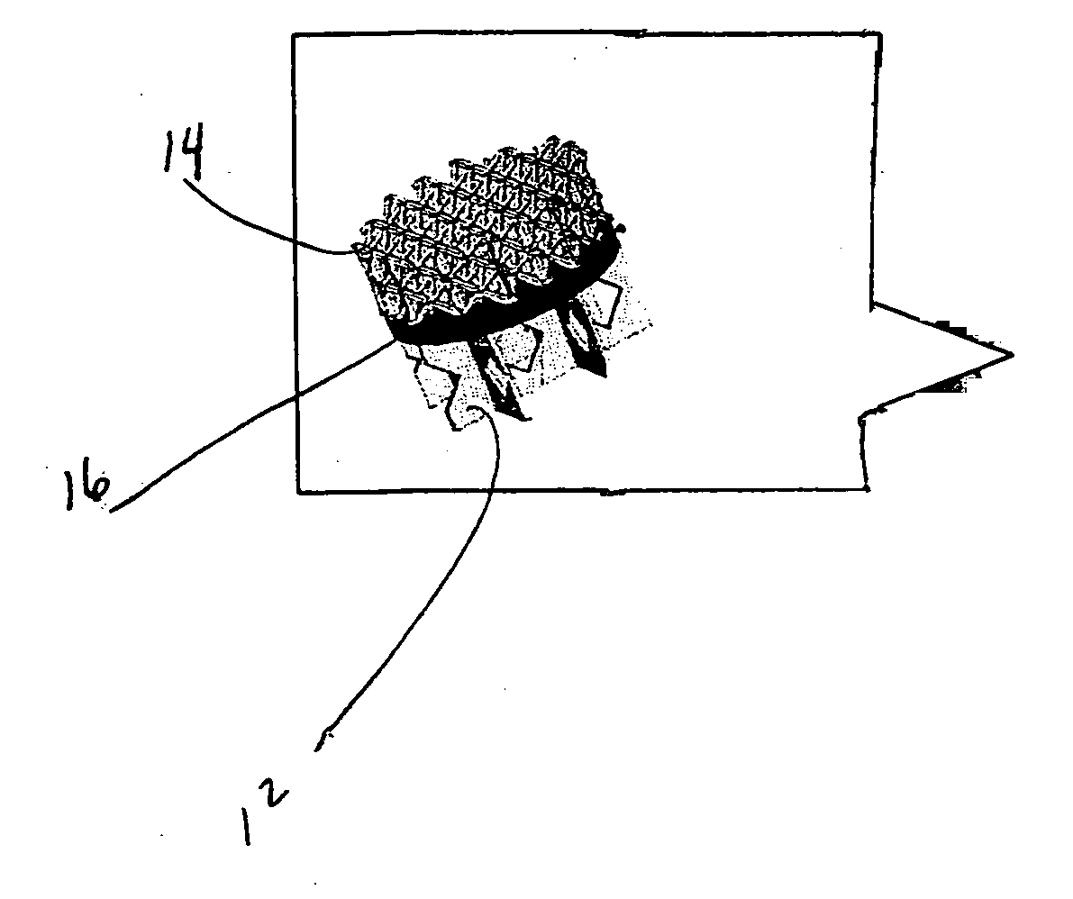
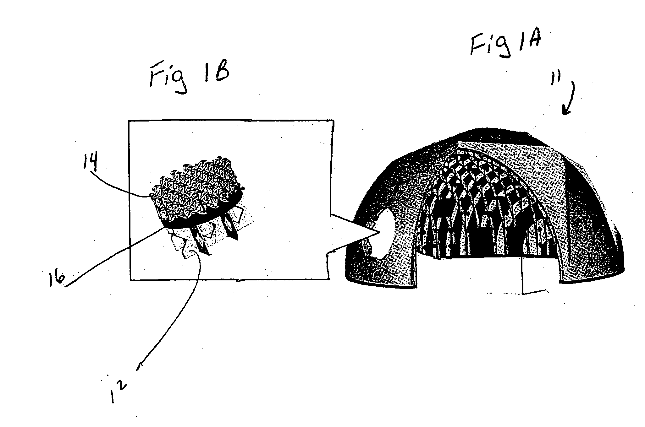
[0045] The present invention relates to a method of forming a porous or partially porous metallic structure having a bearing surface attached directly or indirectly thereto. The structures are particularly but not exclusively applicable for use in the art of soft tissue interlock structures for medical implants and prosthesis.

[0046] The method makes use of laser technology or any other high energy beam by employing a variety of scanning strategies.

[0047] Typical metal and metal alloys employed include stainless steel, cobalt chromium alloys, titanium and its alloys, tantalum and niobium, all, of which have been used in medical device applications. The present invention can be used for such medical device applications where bone and / or soft tissue interlock with the component is required, or where a controlled structure is required to more closely match mechanical properties of the device with surrounding tissue.

[0048] Additionally, the present invention may be employed to enhance...


PUM

PropertyMeasurementUnit
Thicknessaaaaaaaaaa
Thicknessaaaaaaaaaa
Thicknessaaaaaaaaaa

Abstract

A method of forming an implant having a porous tissue ingrowth structure and a bearing support structure. The method includes depositing a first layer of a metal powder onto a substrate, scanning a laser beam over the powder so as to sinter the metal powder at predetermined locations, depositing at least one layer of the metal powder onto the first layer and repeating the scanning of the laser beam.

Description

BACKGROUND OF THE INVENTION [0001] The present invention relates to a device having a porous surface attached directly or indirectly to a bearing surface and a method for forming the same. [0002] In particular, this invention relates to a computer-aided laser apparatus or other suited high energy beam, which sequentially remelts a plurality of powder layers to build a porous layer in a layer-by-layer fashion. [0003] The present invention also includes a method of attaching or connecting a bearing surface directly or indirectly preferably formed from a polymer to the sequentially-built porous part. [0004] The present application is particularly directed toward a method of forming a porous and partially-porous metallic structure having a bearing surface. [0005] The field of free-form fabrication has seen many important recent advances in the fabrication of articles directly from computer-controlled databases. These advances, many of which are in the field of rapid prototyping of artic...

Claims


Application Information

Patent Timeline
IPC IPC(8): A61F2/08
CPCA61F2/30756A61F2/30767A61F2/30907A61F2/3094A61F2/30965A61F2/32A61F2/36A61F2/3877A61F2002/30011A61F2002/30199A61F2002/30243A61F2002/30261A61F2002/30283A61F2002/30329A61F2002/30915A61F2002/3092A61F2002/30968A61F2002/3097A61F2002/30971A61F2002/3401A61F2002/3425A61F2002/3474A61F2220/0025A61F2230/0063A61F2230/0071A61F2230/0082A61F2250/0023A61L27/306A61L27/56B22F3/1055B22F3/1109B22F2999/00B23K26/381B29C37/0082B29C45/14311B29C2045/14327B29L2031/7532C23C4/02C23C4/18C23C24/10C23C26/02B22F2207/11A61F2/30B22F5/10B23K26/382B33Y80/00B33Y10/00B33Y70/00A61F2002/3028A61F2002/30593A61F2002/30594Y02P10/25B22F10/62B22F10/28B22F10/36B22F10/38B22F10/64B22F12/41B22F10/366B22F10/32
Inventor JONES, ERICSUTCLIFFE, CHRISTOPHER J.STAMP, ROBIN
Owner UNIV OF LIVERPOOL
Why Eureka
Try Eureka