Controlling lubrication of moving bodies such as bearings of electric motors

a technology of electric motor bearings and moving bodies, applied in the direction of control/drive circuits, mechanical energy handling, mechanical apparatus, etc., can solve problems such as failure and inability to prevent overheating

Inactive Publication Date: 2007-06-28
MATZAN EUGENE
View PDF14 Cites 11 Cited by
  • Summary
  • Abstract
  • Description
  • Claims
  • Application Information

AI Technical Summary

Benefits of technology

[0003]The present invention relates to an automatic system for lubrication for cyclically operating mechanisms, such as rotary mechanisms, which controls the lubrication as a function of the number of rotations or as a function of the cumulative duration of the mechanism's operating intervals, rather than in predetermined time intervals. The system is especially adapted to control lubrication of the bearings of electric motors The system, in accordance with the present invention, is self-powered, and can provide for maintaining the charge of an internal battery.

Problems solved by technology

These motors usually operate intermittently rather than continuously as required for a particular application, This, however, is not an optimum procedure, wasteful of lubricant and may not prevent overheating and failure if the lubrication does not occur when the conditions would require it.

Method used


Image

  • Controlling lubrication of moving bodies such as bearings of electric motors
  • Controlling lubrication of moving bodies such as bearings of electric motors
  • Controlling lubrication of moving bodies such as bearings of electric motors

Examples


Embodiment Construction

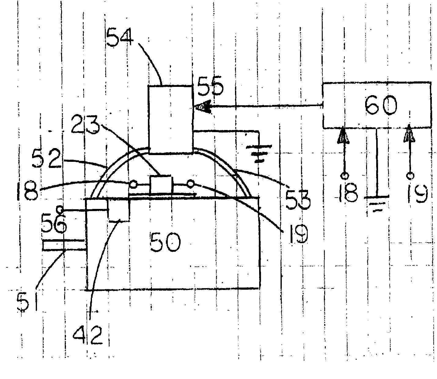
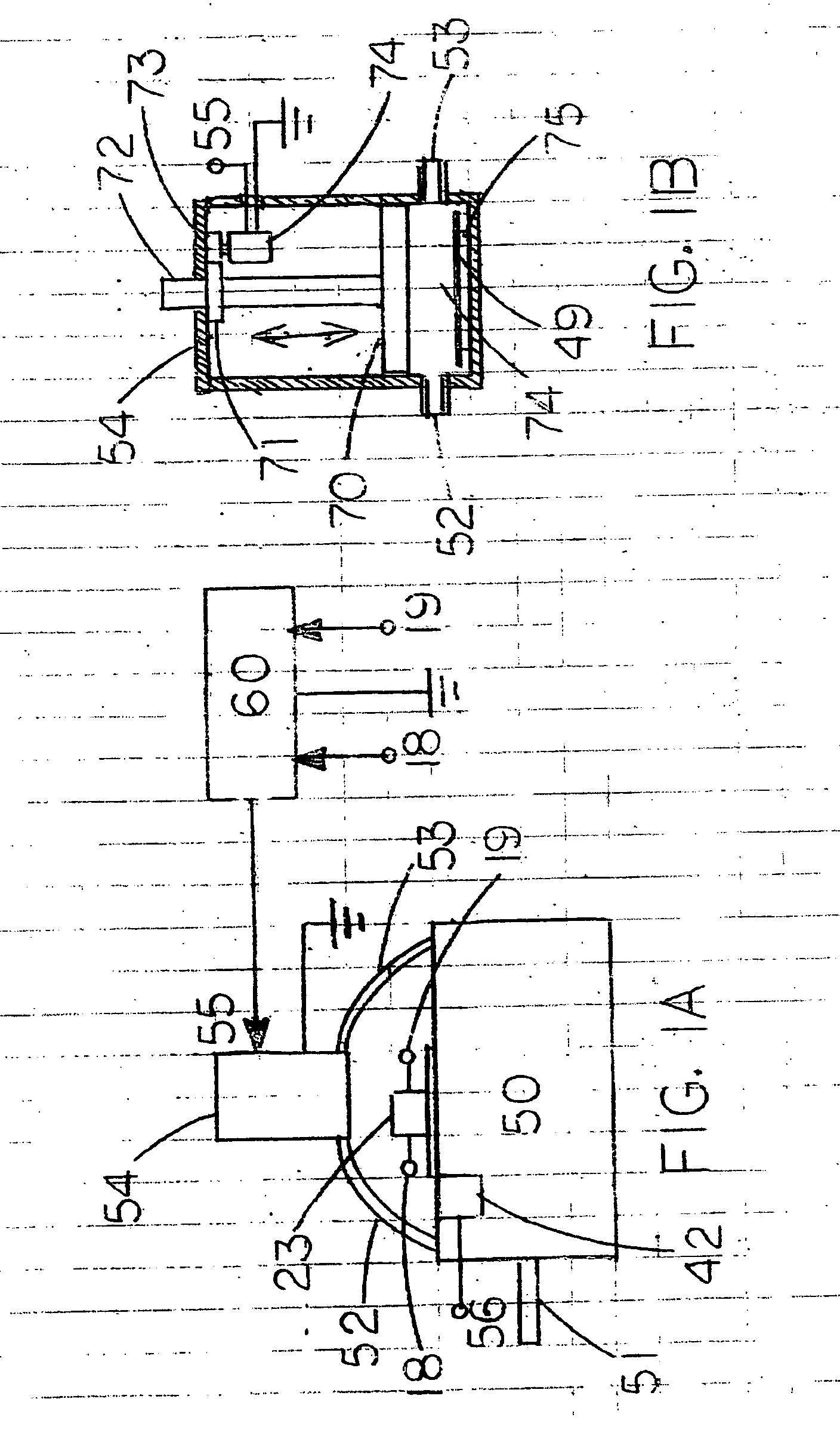
[0013]FIG. 1A depicts an electric motor 50 with a shaft 51, a lubricant dispenser 54 and a sensor / generator 23. The lubricant is injected into the bearings of the motor 50 via tubes 52 and 53. the lubricant dispenser 54 receives it power from the control module 50, which, in turn, receives electric current from the sensor / generator 23 via the terminals 18 and 19. A temperature sensor 42 is attached to the body of the motor 50.

[0014]FIG. 1B shows a cross-section of the cylindrically shaped lubricant dispenser 54 with a piston 70 driven in the direction indicated by the arrows by means of a lead screw 72. The position of the piston 72 determines the variable internal volume 76 of the lubricant dispenser 54 where the lubricant is contained. As the piston 70 moves toward the outlets 52 and 53, it squeezes out the lubricant, which is then injected into the bearings of the motor 50. the lead screw 72 is driven by the rotating gear / nut 71, which is constrained from moving in the vertical d...


PUM


Abstract

A self-powered automatic lubrication system for electric motors utilizes an electromagnetic sensor/generator, which picks up motor vibrations that are synchronous with the rotations of the motor shaft, and in response, generates an alternating current. The current is rectified and used to charge a secondary battery that supplies power to the electronic control system. This control system utilizes the alternating current produced by the sensor/generator as an output signal to time the injection of the lubricant into the motor bearings. The sensor/generator comprises a coil and a permanent magnet suspended by springs within the coil. The magnet moves as the motor vibrates causing electric current to be generated in the coil. The physical parameters of the magnet and the springs are selected such that the movement occurs in resonance with the fundamental frequency of the motor vibrations.

Description

[0001]The present invention relates to a system for controlling injection of lubricants into cyclically moving mechanisms and particularly into the bearings of such mechanisms electric motors, specifically, the bearings of electric motors.BACKGROUND OF THE INVENTION[0002]High power electric motors require periodic lubrication of their bearings to ensure proper operation, long life and to prevent catastrophic failures. Such motors installed in difficult to access locations are equipped with devices, which automatically inject the lubricants into the bearings in defined time intervals. These motors usually operate intermittently rather than continuously as required for a particular application, This, however, is not an optimum procedure, wasteful of lubricant and may not prevent overheating and failure if the lubrication does not occur when the conditions would require it. In accordance with the invention, it has been observed that control of lubrication based on either on a number of...

Claims


Application Information

Patent Timeline
Patent Type & Authority Applications(United States)
IPC IPC(8): F16N11/08
CPCH02K7/08H02K9/19H02K11/0073H02K35/02H02K11/33F16N11/08
Inventor MATZAN, EUGENE
Owner MATZAN EUGENE
Why Eureka
Try Eureka