
Denitrification process and system

a technology of denitration process and denitration system, which is applied in the direction of biological water/sewage treatment, separation process, instruments, etc., can solve the problems of insufficient measurement of influent and effluent concentration of nitrate in determining the proper amount, and weaken the resistance of disease or bacteria

Active Publication Date: 2007-06-28
PARKSON
View PDF3 Cites 17 Cited by
  • Summary
  • Abstract
  • Description
  • Claims
  • Application Information

AI Technical Summary

Benefits of technology

[0015] In one aspect, the invention provides an aqueous denitrification process for a wastewater treatment system. The wastewater treatment system has influent and effluent aqueous flows, a filtration bed harboring microbes, and feed forward and optional feed back control loops. The process comprises the steps of: a) determining influent flow (optionally expressed in...

Problems solved by technology

Fish struggle to breathe, and that can weaken their resistance to disease or bacteria.
Problems can occur during the automatic dosing of chemicals into the treatment system because of inaccuracies of measurements of a chemical present in the system and the variable ratio of chemical to liquid when the liquid flow rate is variable.
However, as discussed above, the measurement of the influent and effluent concentrations of nitrates is insufficient in determining the proper amount of methanol to be fed into the system for denitrification.
Stated another way a methanol dosing system that strictly looks at influent and effluent nitrate would not account for methanol demands associated with varying levels of influent nitrite and DO, thus leading to possible overdosing or underdosing of methanol.
For example, relying on influent nitrate measurements only can result in overdosing because of a drop in influent DO levels.
By the same token, reliance on effluent nitrate measurements can result in underdosing because a low level of measured effluent nitrate misses altogether the fact that a reduction in nitrate levels can simply mean that all the nitrate has been converted to nitrite, which must still be reduced.
Implicit in such an operator-controlled technique is the necessity for an operator to “get up to speed” on system requirements, all of which represents a time consuminglearning curve.”

Method used


Image

  • Denitrification process and system
  • Denitrification process and system
  • Denitrification process and system

Examples


Embodiment Construction

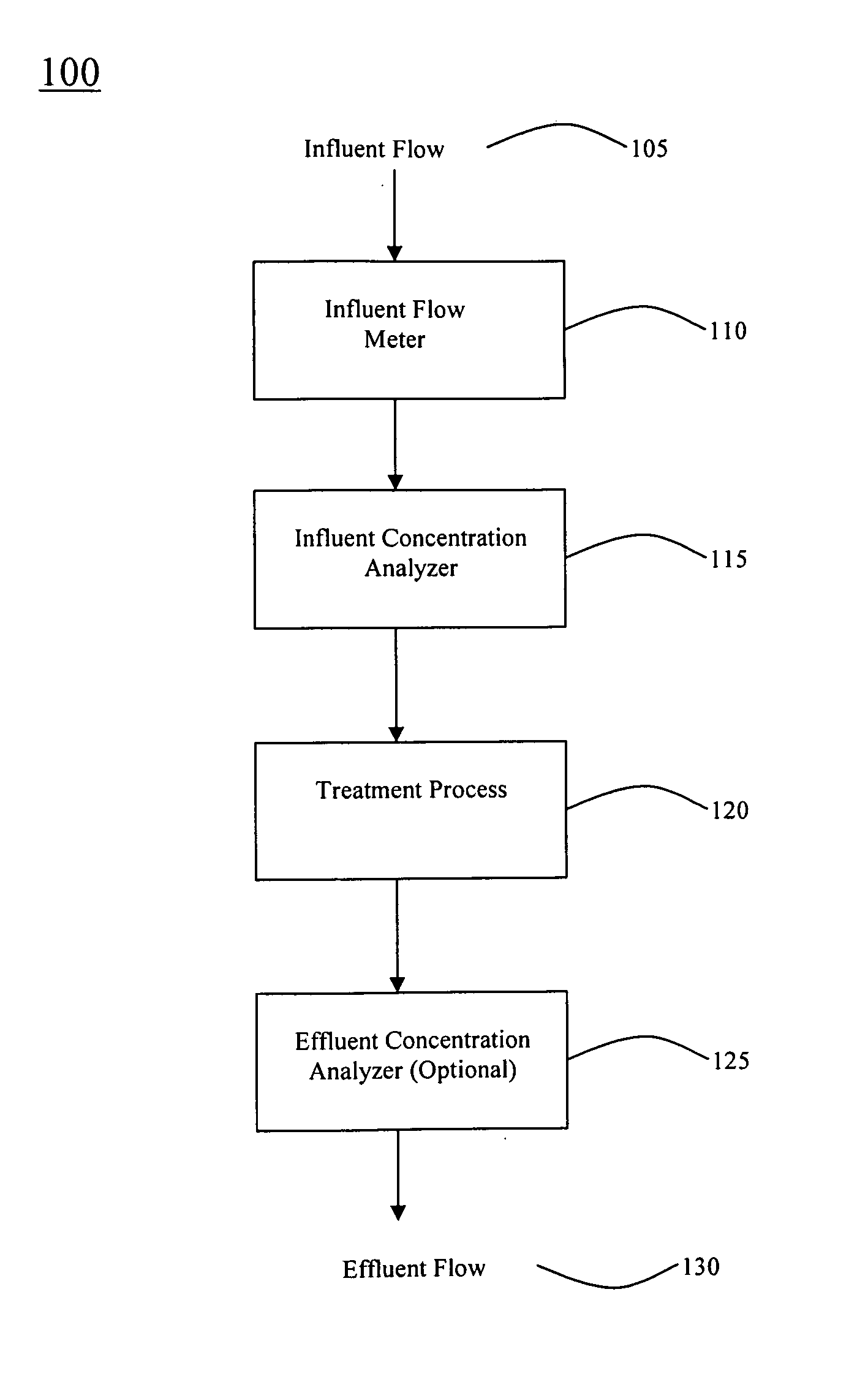
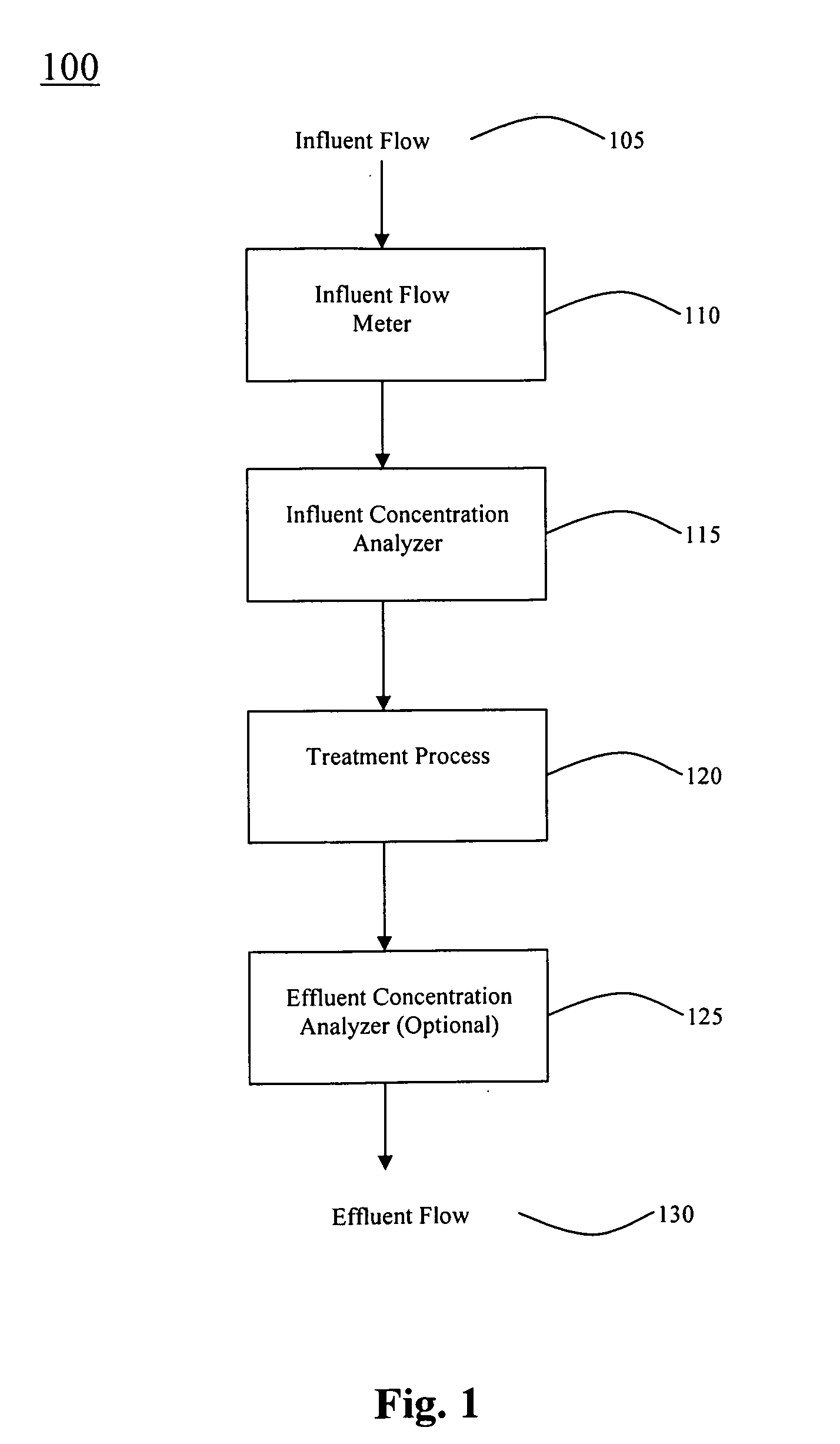
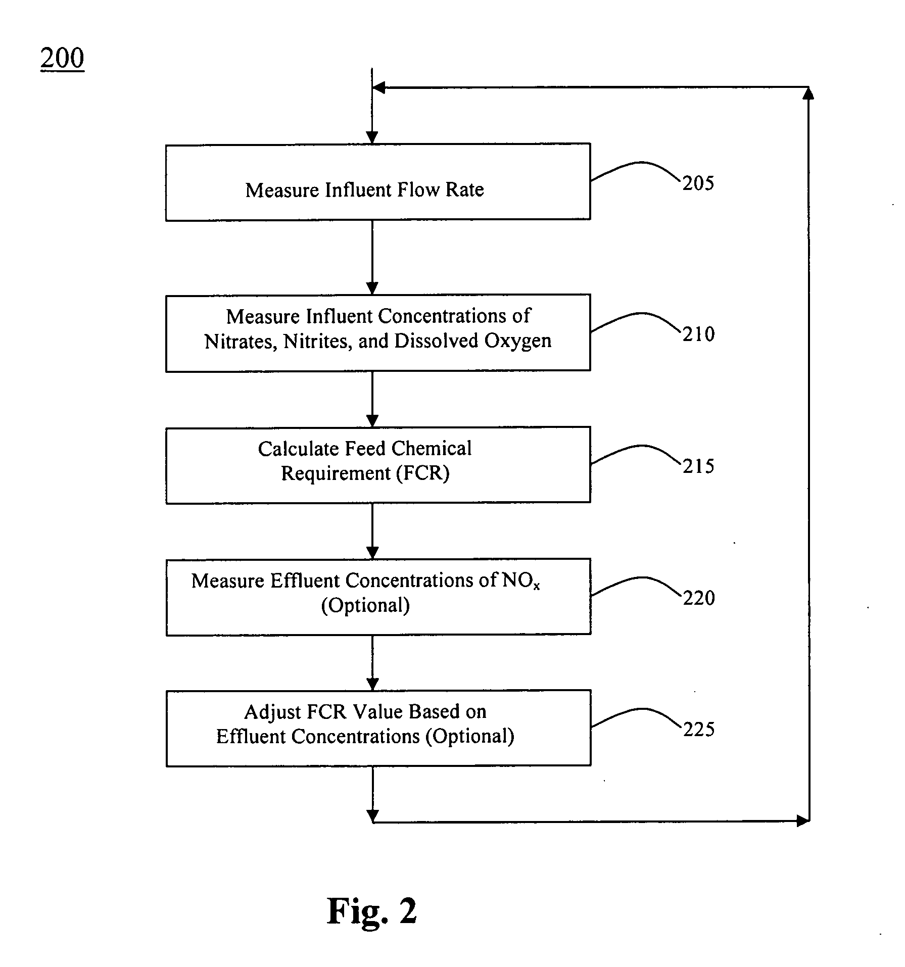
[0021] The present invention is directed to a system and method for performing denitrification of a liquid flow, typically wastewater. Unlike conventional denitrification systems, which rely exclusively on the measurement of influent and effluent concentrations of nitrates to assist in a calculation of a dosage of a feed chemical, typically methanol, and requires an experienced operator to determine “adjustable” and “sensitivity” factors to “fudge” feed chemical dosage values, the present invention also includes the advantages of measuring influent and effluent concentrations of nitrites, as well as the influent concentration of dissolved oxygen, in order to determine a more accurate dosage of methanol to be used in the wastewater treatment process. Hence, no operator-controlled factors are required, as discussed further herein. The invention also encompasses a system in which effluent measurements are merely optional, thus reducing system complexity and cost.

[0022] Referring to FI...


PUM

PropertyMeasurementUnit
Fractionaaaaaaaaaa
Fractionaaaaaaaaaa
Timeaaaaaaaaaa

Abstract

A process and system for denitrification of wastewater. The process includes the steps of measuring an influent flow rate, measuring influent concentrations of nitrates, nitrites, and dissolved oxygen in the wastewater, and using the influent concentrations to determine a nominal amount of methanol to be provided for denitrification. The invention also contemplates the measurement of effluent concentrations of nitrates and nitrites (i.e., NOx), and optionally using the effluent concentrations to adjust the nominal amount of methanol being provided.

Description

CROSS-REFERENCE TO RELATED PATENT APPLICATIONS [0001] This application claims priority to U.S. provisional application 60 / 710,612, filed Aug. 24, 2005, the disclosure of which is incorporated by reference herein in its entirety.BACKGROUND OF THE INVENTION [0002] 1. Field of the Invention [0003] The present invention relates generally to a system and process for wastewater treatment and, in particular, to a system and process for denitrification of wastewater. [0004] 2. Related Art [0005] According to a recent article, which appeared in the Washington Post (“Troubled Waters in the Shenandoah: Death of Smallmouth Bass Brings Attention But No Quick Answers on Improving Quality” By Michael Alison Chandler, Washington Post Staff Writer, Wednesday, Jul. 20, 2005; Page B01), questions are constantly being raised about the quality of the water that feeds into waterways in and around the Shenandoah Valley and, ultimately, the Chesapeake Bay. Among the factors cited in the article, the high n...

Claims


Application Information

Patent Timeline
IPC IPC(8): C02F3/00
CPCC02F3/006C02F3/302G05D21/02C02F2209/22C02F2209/40C02F2209/15C02F3/00
Inventor JANSSEN, DOMINICMCGEHEE, MICHAEL
Owner PARKSON
Learn More