Organic light emitting devices

a light-emitting device and organic technology, applied in the direction of discharge tube luminescnet screen, other domestic articles, natural mineral layered products, etc., can solve the problems of deterioration of the effectiveness of organic light-emitting devices for high-temperature device operation, the stability of currently available devices may in some instances be below expectations, and the number of known organic light-emitting devices has relatively short operational life before luminance drop,

Active Publication Date: 2007-06-28
LG DISPLAY CO LTD
View PDF43 Cites 86 Cited by
  • Summary
  • Abstract
  • Description
  • Claims
  • Application Information

AI Technical Summary

Benefits of technology

[0009] An exemplary embodiment of an organic electroluminescent device comprises an anode, a cathode, and a light emitting zon

Problems solved by technology

While recent progress in organic EL research has elevated the potential of organic EL devices for widespread applications, the operational stability of currently available devices may in some instances be below expectations.
A number of known organic light emitting devices have relatively short operational lifetimes before their luminance drops to some percentage of its initial value.
L824-L826, 1995, may perhaps increase the o

Method used


Image

  • Organic light emitting devices

Examples


Embodiment Construction

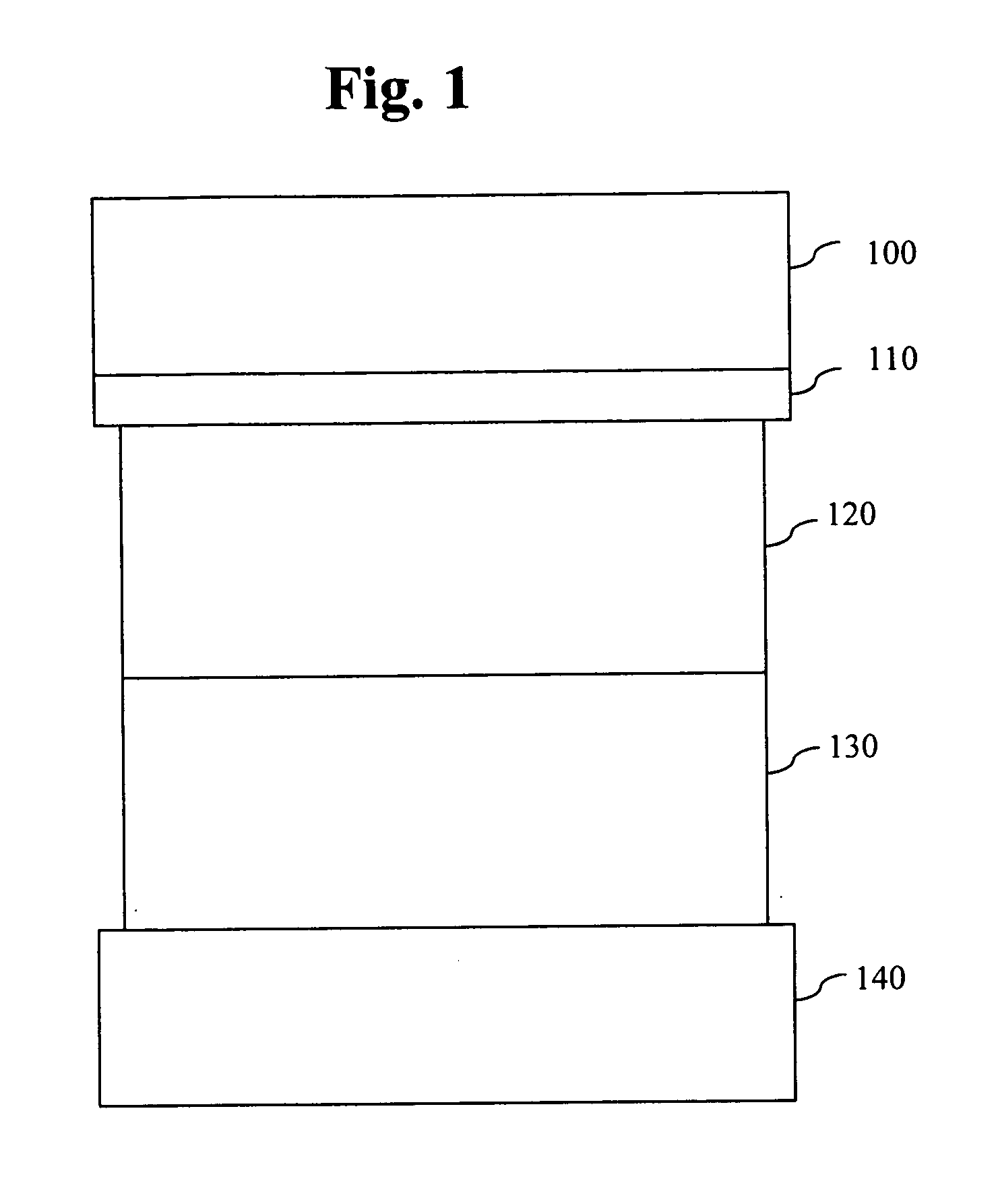
[0013] This invention provides organic light emitting devices (OLEDs) having improved performance.

[0014] Exemplary embodiments of the light emitting devices according to this invention comprise an anode, a cathode and a light emission zone between the anode and cathode. The light emission zone can comprise a wide range of different organic light emitting materials.

[0015] To avoid confusion in understanding the scope of the present invention, the following guidelines can be used:

[0016] The term “layer” indicates a single coating generally having a composition that differs from the composition of an adjacent layer;

[0017] The term “region” refers to a single layer, a plurality of layers such as two, three or more layers;

[0018] The term “zone,” as used in the context of the light emitting zone, refers to a single layer, a plurality of layers, a single functional area in a layer, a plurality of functional areas in a layer, or one or more regions;

[0019] Generally, all regions and la...


PUM

PropertyMeasurementUnit
Magnetic fieldaaaaaaaaaa
Distanceaaaaaaaaaa

Abstract

An organic electroluminescent device includes an anode, a cathode, and a light emitting zone including a material that at least one of reduces triplet/triplet interaction, reduces triplet/singlet interaction, and reduces singlet/singlet interaction.

Description

BACKGROUND OF THE INVENTION [0001] 1. Field of the Invention [0002] This invention relates to optoelectronic devices, and more particularly, to organic light emitting devices (organic EL devices). More specifically, the present invention relates to substantially stable blue light emitting organic EL devices. [0003] 2. Discussion of the Prior Art [0004] An organic electroluminescent (EL) device can be comprised of a layer of an organic luminescent material interposed between an anode, typically comprised of a transparent conductor, such as indium tin oxide, and a cathode, typically a low work function metal such as magnesium, calcium, aluminum, or the alloys thereof with other metals. The EL device functions on the primary principle that under an electric field, positive charges (holes) and negative charges (electrons) are respectively injected from the anode and cathode into the luminescent material and undergo recombination to form excitonic states which subsequently emit light. A ...

Claims


Application Information

Patent Timeline
IPC IPC(8): H01L51/54
CPCH01L51/0039H01L51/0059H01L51/5012H01L51/52Y10S428/917H10K85/115H10K85/631H10K50/11C09K11/06C09K11/07H10K50/80
Inventor AZIZ, HANYPOPOVIC, ZORAN D.HU, NAN-XINGCOGGAN, JENNIFER A.PAINE, ANTHONY J.
Owner LG DISPLAY CO LTD
Why Eureka
Try Eureka