Switched converter with variable peak current and variable off-time control
- Summary
- Abstract
- Description
- Claims
- Application Information
AI Technical Summary
Benefits of technology
Problems solved by technology
Method used
Image
Examples
Embodiment Construction
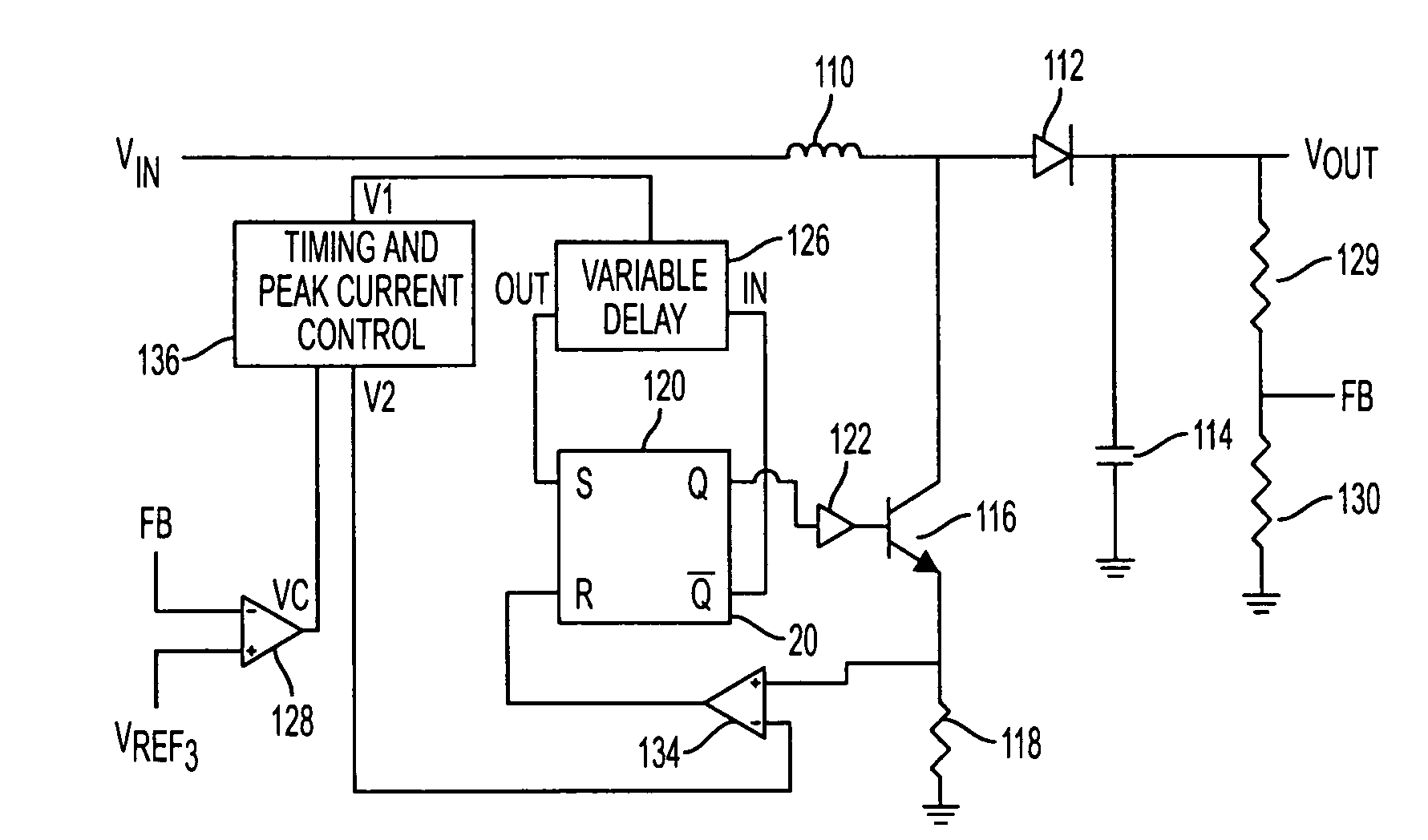
[0026]FIG. 3 is a block diagram of a boost switching regulator in accordance with an embodiment of the present invention. It should be understood that the principles described herein are applicable to boost, buck, and buck-boost current mode switching converters that can provide a regulated output voltage, at either polarity, of any particular desired level from any given DC source. Coupled in series between input node VIN and output node VOUT are inductor 110 and diode 112. Capacitor 114 is connected between the output node and ground. Signal responsive switch 116, shown as a transistor, and sensing resistor 118 are coupled in series between the junction of inductor 110 and diode 112, and ground. Coupled in series between the voltage output node and ground are resistors 129 and 130.
[0027] The base of transistor 116 is coupled to the Q output of latch 120 through switch driver circuit 122. Variable delay circuit 126 is coupled between the / Q output of latch 120 and the set input of ...
PUM
 Abstract
Description
Claims
Application Information
 - R&D
- Intellectual Property
- Life Sciences
- Materials
- Tech Scout
- Unparalleled Data Quality
- Higher Quality Content
- 60% Fewer Hallucinations
Browse by: Latest US Patents, China's latest patents, Technical Efficacy Thesaurus, Application Domain, Technology Topic, Popular Technical Reports.
© 2025 PatSnap. All rights reserved.Legal|Privacy policy|Modern Slavery Act Transparency Statement|Sitemap|About US| Contact US: help@patsnap.com


