Phase interpolator with adaptive delay adjustment

a phase interpolator and delay adjustment technology, applied in the field of phase interpolators, can solve the problems of time delay of such elements is sensitive to the change in incoming data rate, process parameters, erroneous data occurrence in parallelized input data q's, etc., and achieves the effect of simplifying configuration

Inactive Publication Date: 2007-06-28
FUJITSU LTD
View PDF3 Cites 40 Cited by
  • Summary
  • Abstract
  • Description
  • Claims
  • Application Information

AI Technical Summary

Benefits of technology

[0032] An object of the present invention is to provide a phase interpolator which secures phase relations between the reference signals and the interpolated signal and can be applied to realize devices with a smaller and simpler configuration.
[0034] The first phase interpolator according to the present invention is a phase interpolator comprising: a first adjustable delay unit delaying a first reference clock signal to generate an interpolated clock signal with variable delay amount; a second adjustable delay unit delaying a second reference clock signal which has different phase from the first reference clock signal to generate a signal for comparison with variable delay amount; a phase comparator unit comparing phase of the interpolated clock signal and the signal for comparison and outputting a comparison result signal; and a delay amount control unit controlling the delay amount of the first adjustable delay unit and the second adjustable delay unit based on the comparison result signal to decrease phase difference between the interpolated clock signal and the signal for comparison.
[0035] The second phase interpolator according to the present invention is a phase interpolator comprising: a first adjustable delay unit delaying a first reference clock signal to generate an interpolated clock signal with variable delay amount; a second adjustable delay unit delaying the interpolated clock signal to generate a signal for comparison with variable delay amount; a phase comparator unit comparing a phase of a second reference clock signal, which has a different phase from the first reference clock signal, and the signal for comparison, and outputting a comparison result signal; and a delay amount control unit controlling the delay amount of the first adjustable delay unit and the second adjustable delay unit based on the comparison result signal to decrease the phase difference between the second reference clock signal and the signal for comparison.
[0036] According to the present invention, the phase relations between the reference signals and the interpolated signal are secured by a feedback loop in the phase interpolator. Therefore, there is no need to provide additional circuits which compensate phase mismatch between the reference signals and the interpolated signal when configuring devices using the phase interpolator.
[0037] As a result, the present invention can provide the phase interpolator which can be applied to realize devices of smaller and simpler configuration.

Problems solved by technology

Moreover, there are different kinds of time jitter and variation in delay compensation elements.
The time delays of such elements are also sensitive to change in incoming data rate, process parameters and temperature.
If phase error occurs erroneous data will exist in the output of the data recovery system.
This phase shift causes erroneous data occurrence in parallelized input data Q's.
However, phase mismatch occurs because t_dly varies with values of g1, g2, and operating conditions.
Addition of these non-linearity decoders increases the complexity and circuit scale of the clock data recovery system.
Due to the large scale of the circuit and time delays in each circuit block, the phase error cannot be compensated immediately.
As a result, there will be erroneous data in the recovered data.
This will result in errors in the demultiplexed data.
In the conventional phase interpolator, an interpolated signal is generated by analog elements which have inherent operational delay and this delay is directly reflected in the phase delay of the interpolated signal.
Therefore, a clock data recovery system or the like using the phase interpolator becomes bigger and more complex while instability of phase relations between the reference signals and the interpolated signal remains.

Method used


Image

  • Phase interpolator with adaptive delay adjustment
  • Phase interpolator with adaptive delay adjustment
  • Phase interpolator with adaptive delay adjustment

Examples


Embodiment Construction

[0054] The phase interpolator of the present invention may be embedded in an integrated circuit or be built from discrete elements. The phase interpolator of the present invention is also applicable to a phase locked loop or feedback system in which periodic clocks and / or signals are used to synchronize input data. It can also be used to synchronize system clocks in remote parts of a logic or digital system.

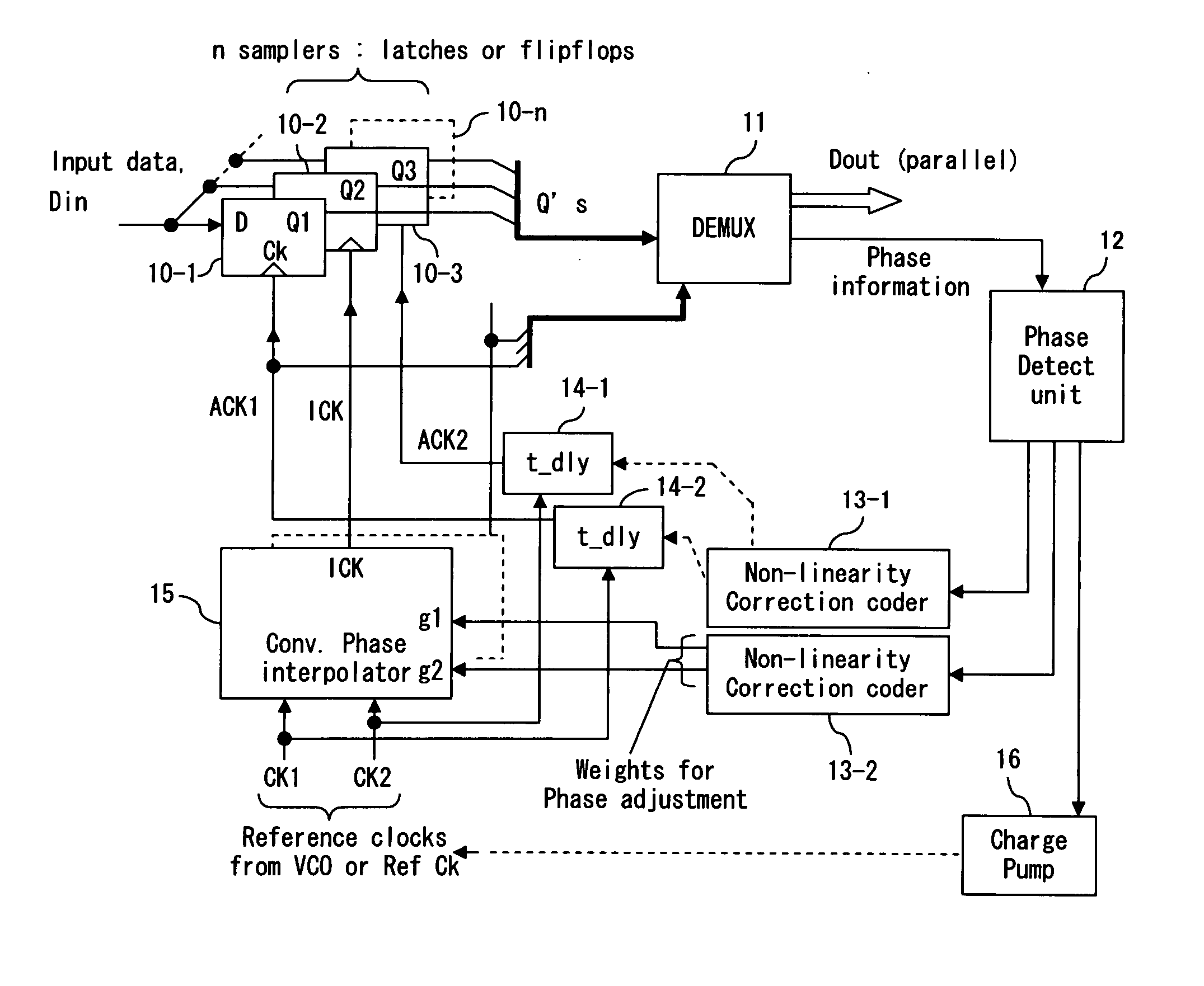
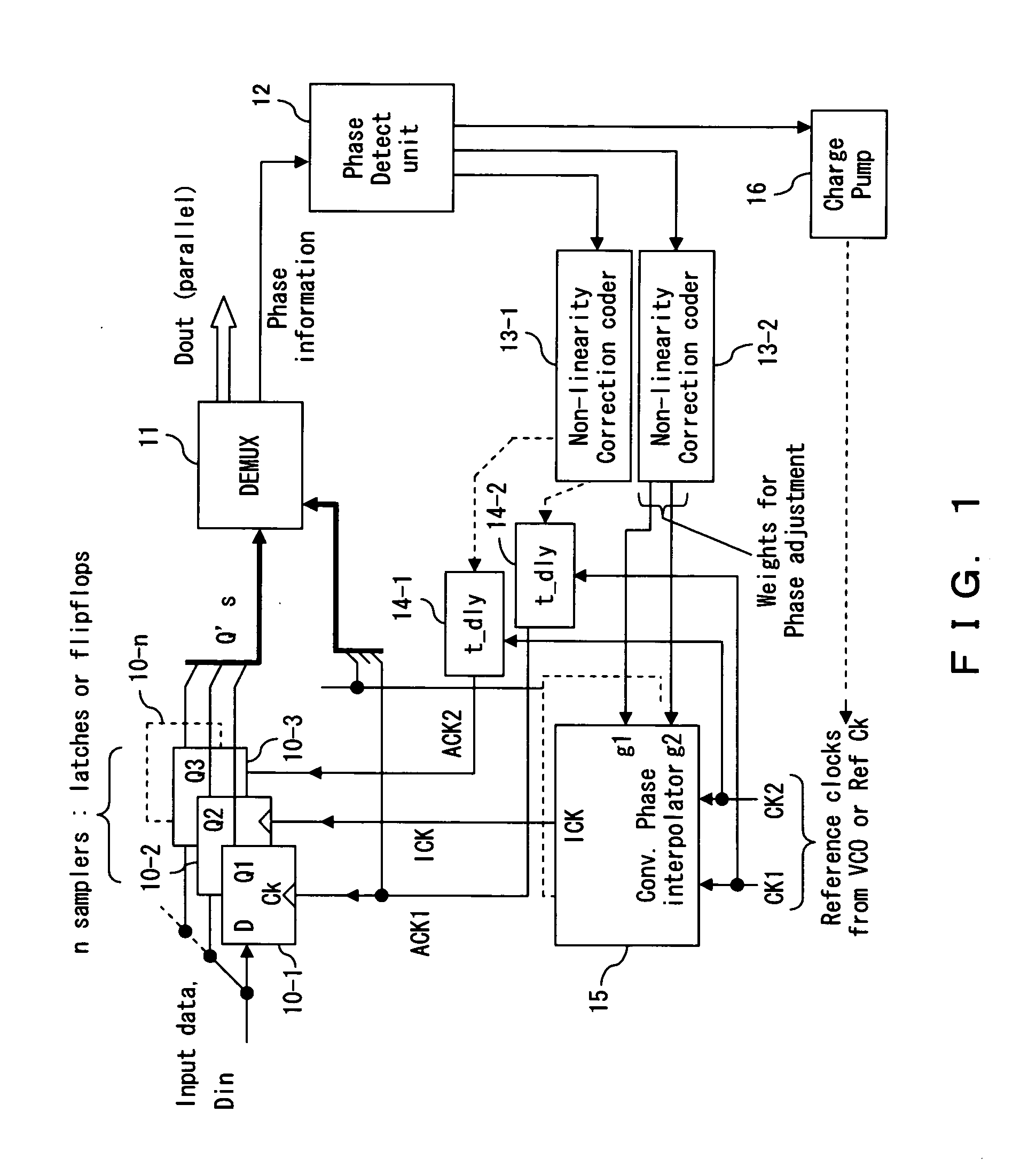
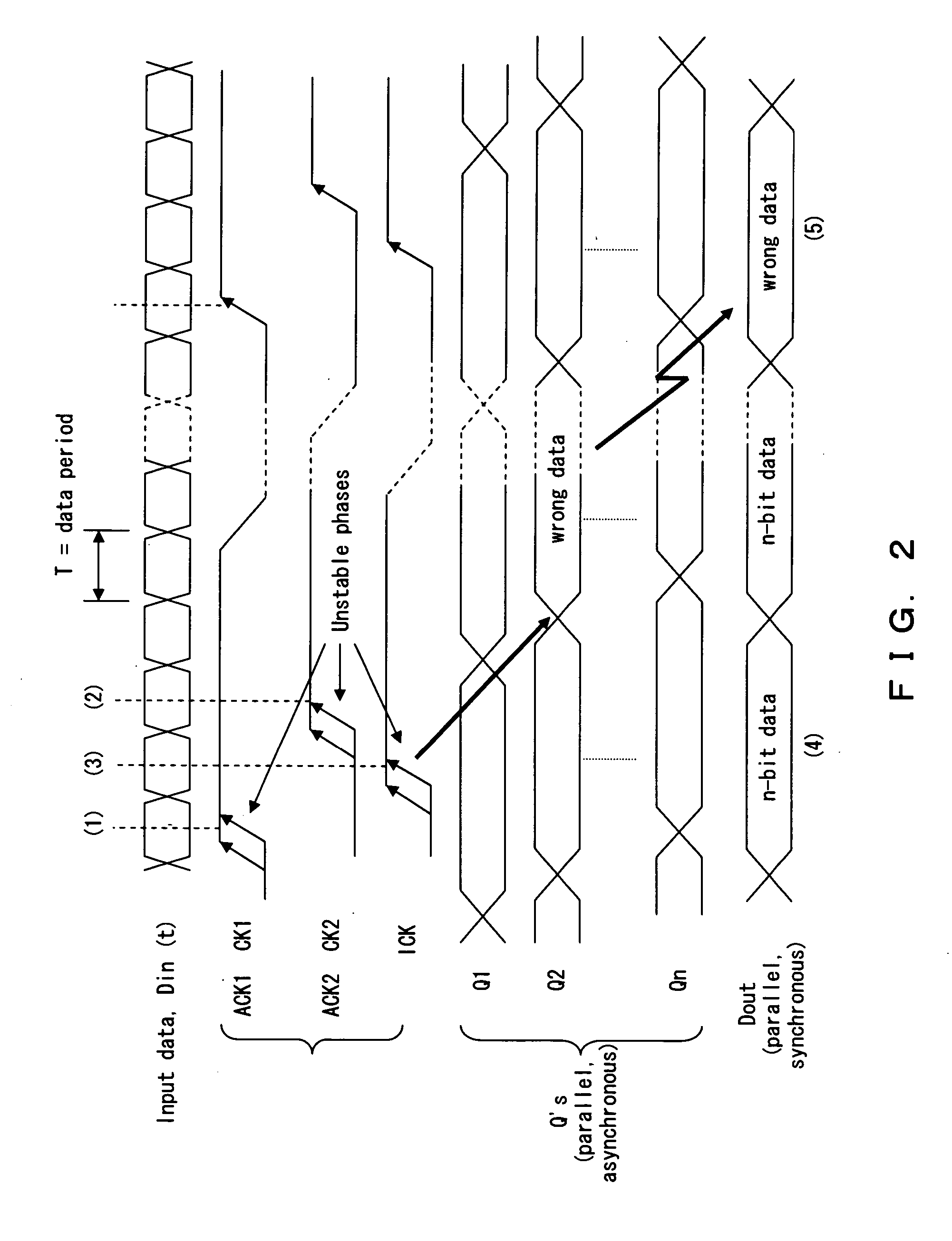
[0055] Delay time (t_dly) exists in the interpolated clock (ICK) generated by a conventional phase interpolator. To compensate for such a delay time, both of input reference clocks (CK1, CK2) are delayed to generate adjusted clocks (ACK1, ACK2). However, phase mismatch occurs because t_dly varies with ICK's phase and operating conditions.

[0056] The phase interpolator of the present invention produces an ICK which has stable phase relations with input reference clocks (CK1, CK2).

[0057] In the phase interpolator of the present invention, ICK are adjusted by a feedback loop such ...


PUM


Abstract

The phase interpolator includes two adjustable delays 30 and 31, phase comparator 32 which detects a phase difference between a signal delayed by the adjustable delay 30 and a signal delayed by the adjustable delay 31, an integrator 33 which integrates the outputs of the phase comparator 32 and multipliers 34-1 and 34-2 which set a control voltage for the adjustable delays 30 and 31. The feedback loop comprising phase comparator 32 and integrator 33 controls a delay amount of the adjustable delay 30 thereby securing a phase relation between {ACK1, ACK2} and ICK to achieve a stable ICK phase.

Description

BACKGROUND OF THE INVENTION [0001] 1. Field of the Invention [0002] The present invention relates to a phase interpolator, particularly, that of a Clock Data Recovery (CDR) system. [0003] 2. Description of the Related Arts [0004] Phase interpolators are widely used to adjust phase differences among system clocks in Clock Data Recovery (CDR) systems and phase detection systems, in which accurate interleaving clocks are required for the front-end samplers to latch the input data. [0005] Conventional phase interpolators (PI) use analog elements (adder, multiplier or mixer, amplifier, etc.) to adjust a phase difference between two reference clock(s). Since time delays exist in those analog elements, delay compensation elements are necessary to adjust phase among reference clocks and interpolated clock. Moreover, there are different kinds of time jitter and variation in delay compensation elements. The time delays of such elements are also sensitive to change in incoming data rate, proce...

Claims


Application Information

Patent Timeline
Patent Type & Authority Applications(United States)
IPC IPC(8): H03K5/19H03K5/13H03K5/131H03L7/00
CPCH03K2005/00052H03L7/081H03L7/091H04L7/0337
Inventor CHEUNG, TSZSHING
Owner FUJITSU LTD
Why Eureka
Try Eureka