Clock and data recovery with extended integration cycles

a clock and data recovery technology, applied in the field of clock and data recovery systems, can solve the problems of extreme clock skew sensitivity of the cdr system, capture of erroneous data, etc., and achieve the effect of optimizing the clock recovery circuitry, maximizing the signal-to-noise ratio, and minimizing the possibility of latching erroneous data

Inactive Publication Date: 2007-06-28
AVAGO TECH WIRELESS IP SINGAPORE PTE
View PDF14 Cites 17 Cited by
  • Summary
  • Abstract
  • Description
  • Claims
  • Application Information

AI Technical Summary

Benefits of technology

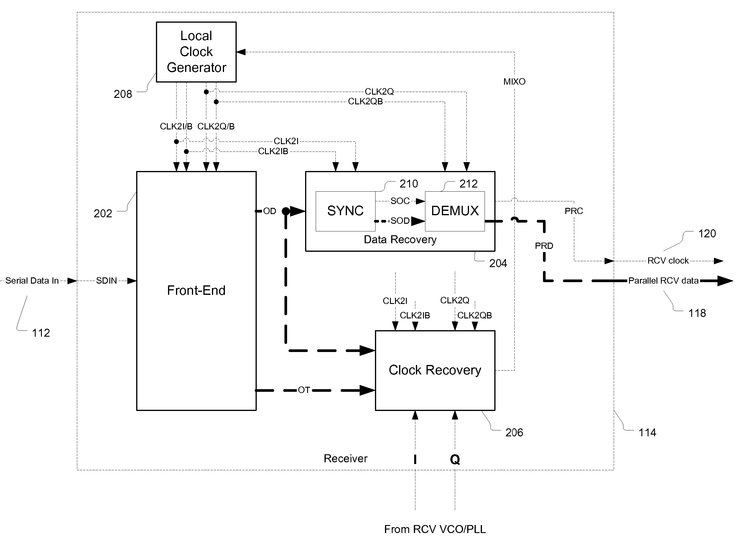
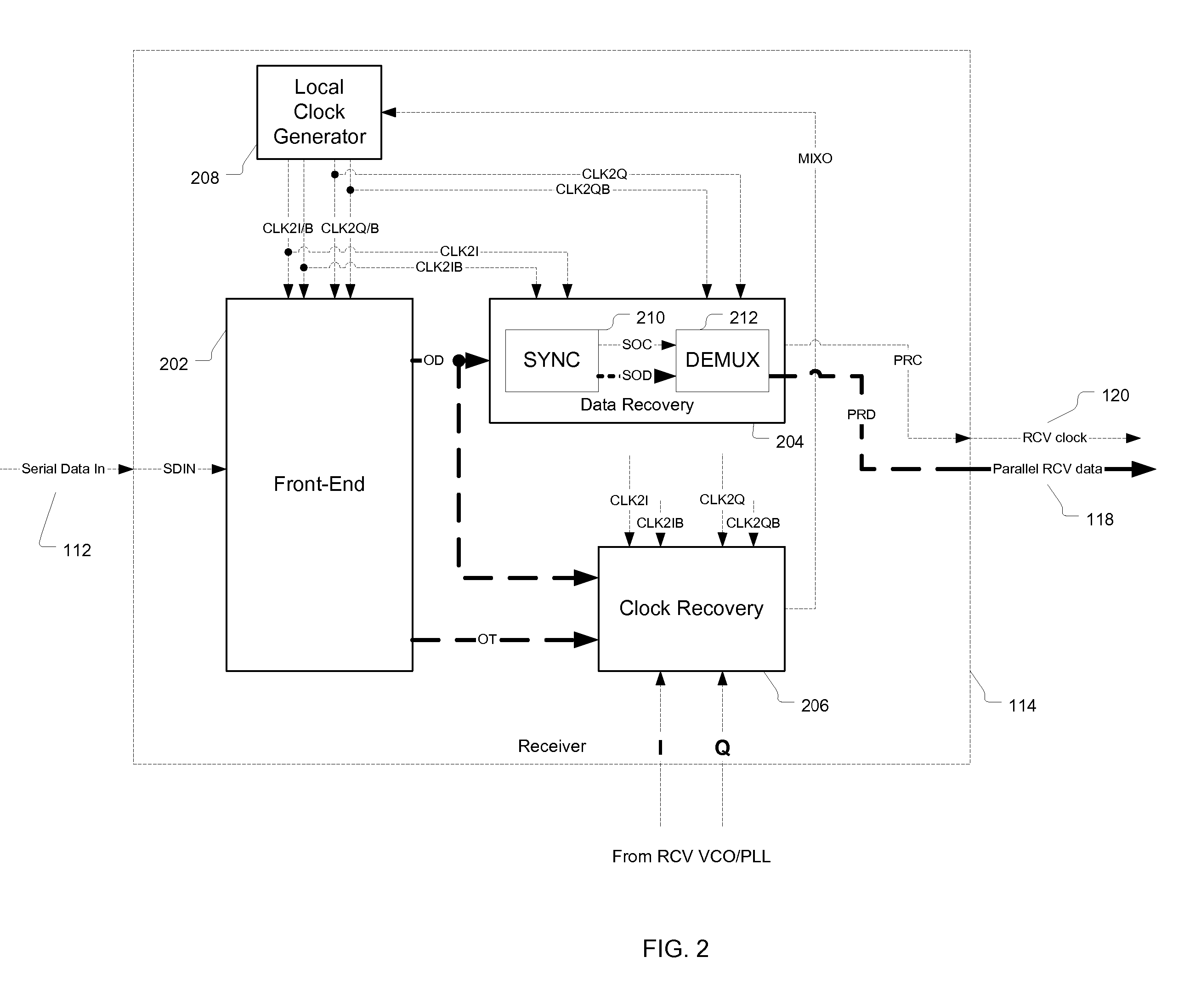
[0008] To address the above-discussed deficiencies ofthe prior art, clock and data recovery circuitry according to one embodiment ofthe present invention includes a four-way interleaved sampler, where each integrator in the sampler integrates the input data for two unit intervals (UIs) and each integrator is sampled at or near the middle of its two-UI integration cycle. In an exemplary 10-GHz system, the reset cycle of each integrator may begin many tens of picoseconds after the data is sampled. Since the signal is sampled near the center of the integration cycle and is not highly proximate to the time of the integrator reset, the latch signal has a window of uncertainty extending into the length of a data bit cell with little possibility of latching erroneous data. The sensitivity of the clock recovery circuitry may be optimized by centering the latch function over the time of highest signal level, thereby maximizing signal-to-noise ratio.

Problems solved by technology

Generally, CDR systems suffer from extreme sensitivity to clock skew between clock domains within the CDR circuit.
Given the high-speed nature of these systems and the relatively low noise margin, even minor errors in the alignment of clock edges to data availability may result in erroneous data being captured.

Method used


Image

  • Clock and data recovery with extended integration cycles
  • Clock and data recovery with extended integration cycles
  • Clock and data recovery with extended integration cycles

Examples


Embodiment Construction

[0019] Reference herein to “one embodiment” or “an embodiment” means that a particular feature, structure, or characteristic described in connection with the embodiment can be included in at least one embodiment of the invention. The appearances of the phrase “in one embodiment” in various places in the specification are not necessarily all referring to the same embodiment, nor are separate or alternative embodiments mutually exclusive of other embodiments.

[0020] Note that, throughout this text and in the figures, a signal name with lowercase “p” or “n” appended to it, is used to indicate the “positive” or “negative” element, respectively, of a differential pair. Similarly, an uppercase “B” for “bar” appended to a signal name (potentially prior to an appended lowercase “p” or “n”) is used to indicate the inverted copy of that signal. Finally, an uppercase “Q” appended to a signal name indicates that it is the quadrature-phase (i.e., 90-degree) shifted version ofthat signal. For exa...


PUM


Abstract

Clock and data recovery circuitry includes an interleaved sampler having multiple integrators, where at least one of the integrators integrates the input data for at least two unit intervals (UIs). One embodiment includes a four-way interleaved sampler, where each integrator in the sampler integrates the input data for two UIs, where each integrator is sampled at or near the middle of its two-UI integration cycle. In an exemplary 10-GHz system, the reset cycle of each integrator may begin many tens of picoseconds after the data is sampled. Since the signal is sampled near the center of the integration cycle and is not highly proximate to the time of the integrator reset, the latch signal has a window of uncertainty extending into the length of a data bit cell with little possibility of latching erroneous data. The sensitivity of the clock recovery circuitry may be optimized by centering the latch function over the time of highest signal level, thereby maximizing signal-to-noise ratio.

Description

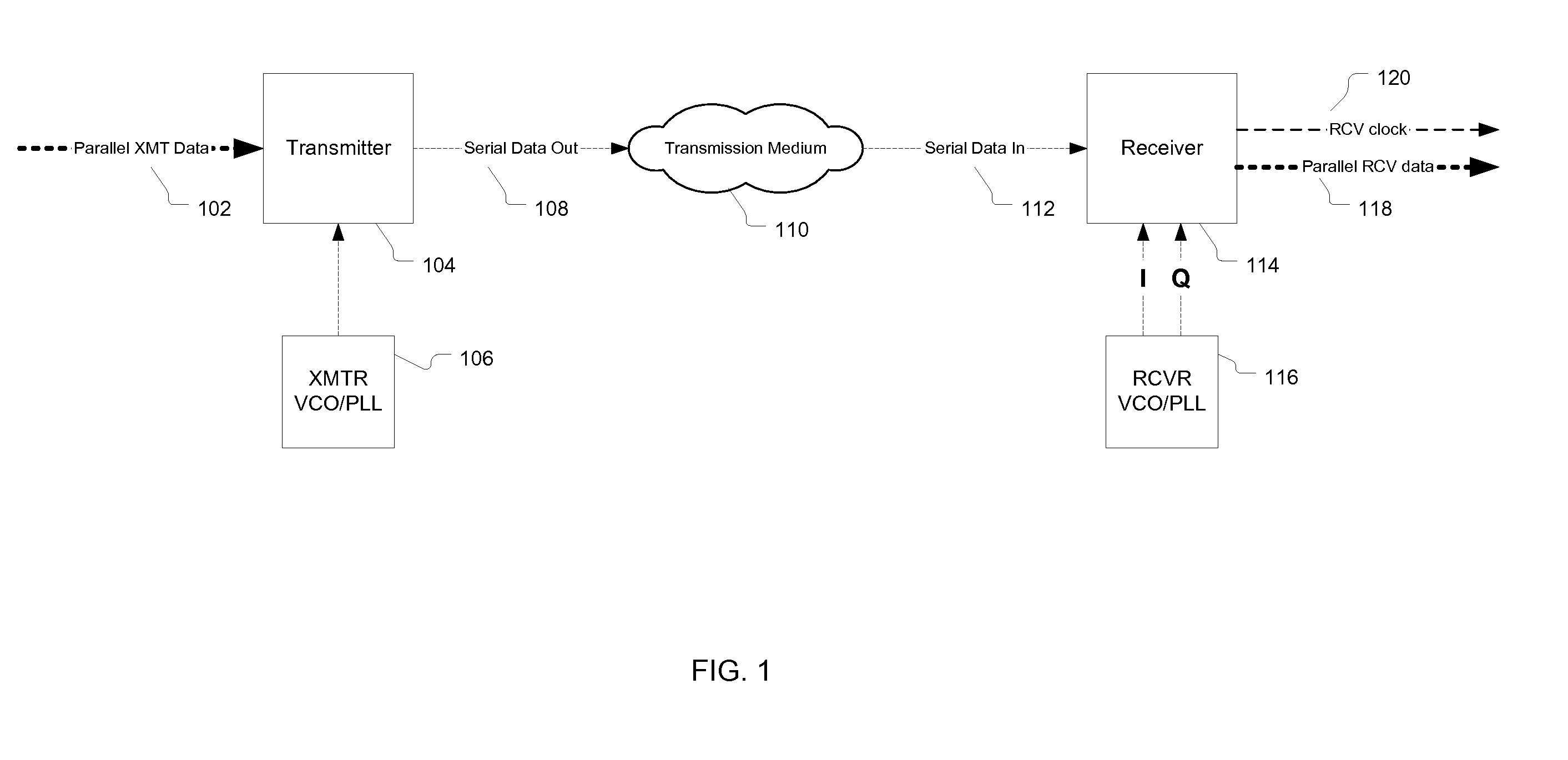
RELATED APPLICATIONS [0001] The subject matter of this application is related to the subject matter of U.S. patent application Ser. No. 09 / 947,488, filed on Sep. 6, 2001 as attorney docket no. Larsson 25-1 (“Larsson 25-1”), and U.S. patent application Ser. No. 09 / 955,424, filed on Sep. 18, 2001 as attorney docket no. Larsson 26-13-2 (“Larsson 26-13-2”), the teachings of both of which are incorporated herein by reference. [0002] This application is a continuation of U.S. patent application Ser. No. 10 / 298,892, filed on Nov. 18, 2002 as attorney docket no. Laturell 54-5-1, incorporated herein by reference in its entirety.BACKGROUND OF THE INVENTION [0003] 1. Field of the Invention [0004] The present invention relates to clock and data recovery systems and, more specifically, to integrator-based front ends and bang-bang phase detectors for clock and data recovery. [0005] 2. Description of the Related Art [0006] High-speed (e.g., 2.5-3.125 Gb / s) serial links are commonly used for chip-t...

Claims


Application Information

Patent Timeline
Patent Type & Authority Applications(United States)
IPC IPC(8): H04L7/00H03L7/08H03L7/081H03L7/089H04L7/033
CPCH03L7/08H03L7/0812H03L7/0893H04L7/033H04L7/0332
Inventor LATURELL, DONALD R.METZ, PETER C.YU, BAIYING
Owner AVAGO TECH WIRELESS IP SINGAPORE PTE
Why Eureka
Try Eureka